Multiphase motors with single point sensing based commutation

a multi-phase motor and sensing technology, applied in the direction of electronic commutators, motor/generator/converter stoppers, dynamo-electric converter control, etc., can solve the problems of unreliable motor performance, simple, unreliable time domain-based multi-phase switching, etc., and achieve reliable motor performance.

Inactive Publication Date: 2005-05-10
PETERSEN TECH
View PDF13 Cites 50 Cited by
  • Summary
  • Abstract
  • Description
  • Claims
  • Application Information

AI Technical Summary

Benefits of technology

[0019]The above embodiment incorporating a sensible system, single sensor and a control system that operates with a predetermined commutational sequence of phases also requires that to achieve consistent adequate start-up torque the motor control start-up sequence provides for the presence of a designated motor starting phase working in conjunction with an alignment phase. A control circuit of the motor responds to a start input to energize those stator windings constituting an alignment phase prior in commutational sequence to the starting phase. This alignment phase is characterized in exhibiting a phase stable position exhibiting a zero torque or stable position when the alignment phase is held energized. To align the rotor for motor start-up, the alignment phase is energized to drive the rotor toward a phase stable condition to an extent providing for adequate start-up torque upon subsequent energization of a designated starting phase. Following such start-up, the sensible system phase commutating information attributes, performing in concert with the single sensor, and the control system provide reliable motor performance under rather extended load variations. Testing of the system has revealed continued proper commutational performance following loads reaching a stalled condition.

Problems solved by technology

With progress in these fields, classically designed electric motors, for example, utilizing brush-based commutation, have been found to be unacceptable or, at best, marginal performers.
The electric motors initially utilized for these drives were relatively expensive and incorporated a variety of refinements particularly necessitated with the introduction of rotating disc memory.
By contrast, simple, time domain-based multiphase switching has been considered to be unreliable and impractical since the rotation of the rotor varies in terms of speed under load as well as in consequence of a variety of environmental conditions.
Thus, the significant cost advantages associated with the integration of the positional sensor and the control circuit in a single chip is lost.
The resultant cost factor generally precludes the use of efficient multiphase motors with very low cost applications such as electrical circuit cooling fans.
However, as the era of electronic-based systems expands, battery-based power limitations are setting the stage for much higher motor efficiency requirements.
Such phasing is highly inefficient, the motors necessarily experiencing zero torque based commutation switching.

Method used


Image

  • Multiphase motors with single point sensing based commutation
  • Multiphase motors with single point sensing based commutation
  • Multiphase motors with single point sensing based commutation

Examples


Embodiment Construction

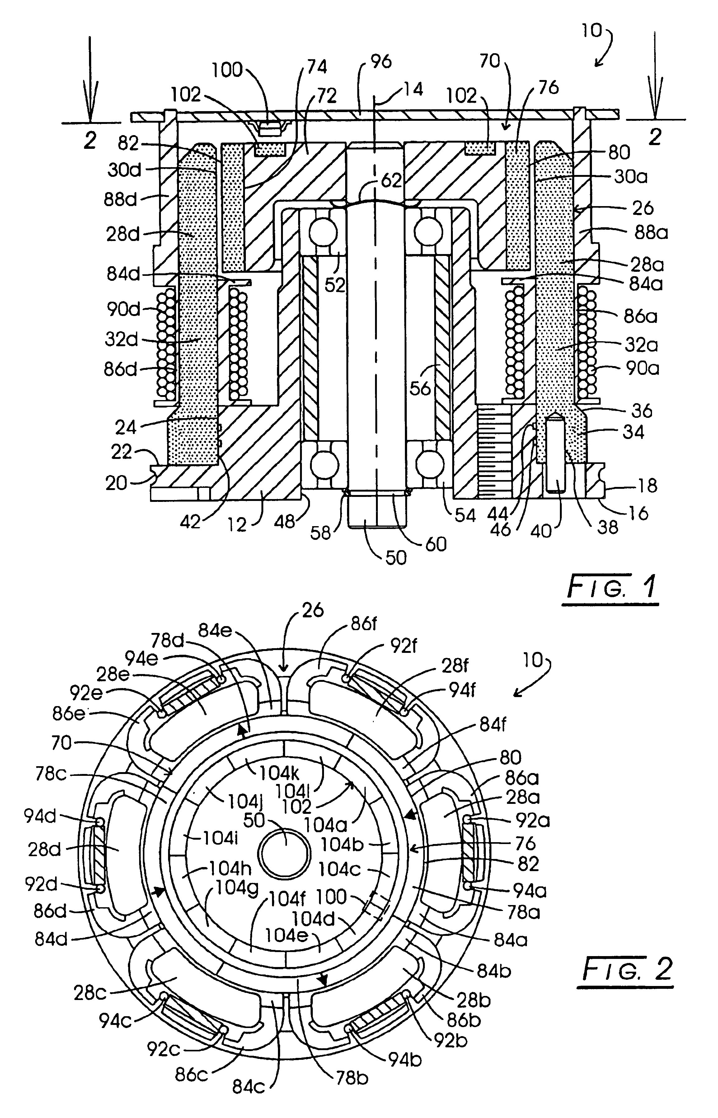
[0103]Referring to FIGS. 1 and 2, a multiphase D.C. PM motor incorporating the single sensor based control features of the invention is revealed in general at 10. As noted earlier, the term “multiphase” as used herein is intended to mean three or more phases. Such motors are further characterized in that the number of rotor poles will be different than the number of stator poles. Motor 10 is seen in FIG. 1 to be formed with an aluminum base 12 disposed symmetrically about a rotor axis 14 and having a circular flange represented in general at 16, the circular edge 18 of which carries a connecting groove 20 employed for mounting motor 10 within an appliance. Supported upon the annular rearward surface 22 of flange 16, as well as in conjunction with a recessed cylindrical based shoulder portion 24 is a pressed powdered metal stator core assembly represented generally at 26. The six pole, integrally formed stator core assembly 26, as represented in FIG. 2, is seen to incorporate spaced ...


PUM


Abstract

System, method and apparatus for commutating a multiphase motor utilizing a single sensor. Commutation is carried out by employing a sensible system which incorporates phase commutating transition attributes. A motor is started by assigning a starting phase for a given direction of motor direction. An aligning phase initially is energized to orient the rotor so as to provide adequate starting phase start-up torque. Following such alignment and start-up, the motor is operated in response to transitions of the sensible system. In one aspect, a reference phase attribute may be incorporated in the sensible system to provide a mandated reference phase energization when the rotor is oriented for reference phase activation. Further described is a sensible system magnetic region configuration which is combined with a single package Hall effect sensor to provide three-phase unipolar and four-phase commutation with absolute phase defining information.

Description

CROSS-REFERENCE TO RELATED APPLICATIONS[0001]This application claims the benefit of provisional application No. 60 / 454,767, filed 14 Mar. 2003.STATEMENT REGARDING FEDERALLY SPONSORED RESEARCH[0002]Not applicable.BACKGROUND OF THE INVENTION[0003]Investigators in the electric motor arts have been called upon to significantly expand motor technology from its somewhat static status of many decades. Improved motor performance particularly has been called for in such technical venues as computer design and secondary motorized systems carried by vehicles, for example, in the automotive and aircraft fields. With progress in these fields, classically designed electric motors, for example, utilizing brush-based commutation, have been found to be unacceptable or, at best, marginal performers.[0004]From the time of its early formation, the computer industry has employed brushless D.C. motors for its magnetic memory systems. The electric motors initially utilized for these drives were relatively...

Claims


Application Information

Patent Timeline
Patent Type & Authority Patents(United States)
IPC IPC(8): H02K29/06H02K29/08H02P6/00H02K21/12H02P6/20
CPCH02K21/12H02K29/08H02P6/22H02P6/181H02P6/20H02P6/16
Inventor PETERSEN, CHRISTIAN C.
Owner PETERSEN TECH
Why Eureka
Try Eureka