Touch panel-including illuminator and reflective liquid-crystal display device

a liquid crystal display device and touch panel technology, applied in the direction of identification means, instruments, lighting and heating apparatus, etc., can solve the problems of touch panel (particularly the transparent electrodes of the touch panel), touch panel breaks down, and the effective light utilization efficiency is substantially considerably poor. , to achieve the effect of good perpendicular directivity, excellent both in light utilization efficiency and frontal luminan

a liquid crystal display device and touch panel technology, applied in the direction of identification means, instruments, lighting and heating apparatus, etc., can solve the problems of touch panel (particularly the transparent electrodes of the touch panel), touch panel breaks down, and the effective light utilization efficiency is substantially considerably poor. , to achieve the effect of good perpendicular directivity, excellent both in light utilization efficiency and frontal luminan

US6891530B2Inactive Publication Date: 2005-05-10NITTO DENKO CORP

Image

  • Touch panel-including illuminator and reflective liquid-crystal display device
  • Touch panel-including illuminator and reflective liquid-crystal display device
  • Touch panel-including illuminator and reflective liquid-crystal display device

Examples


reference example 1

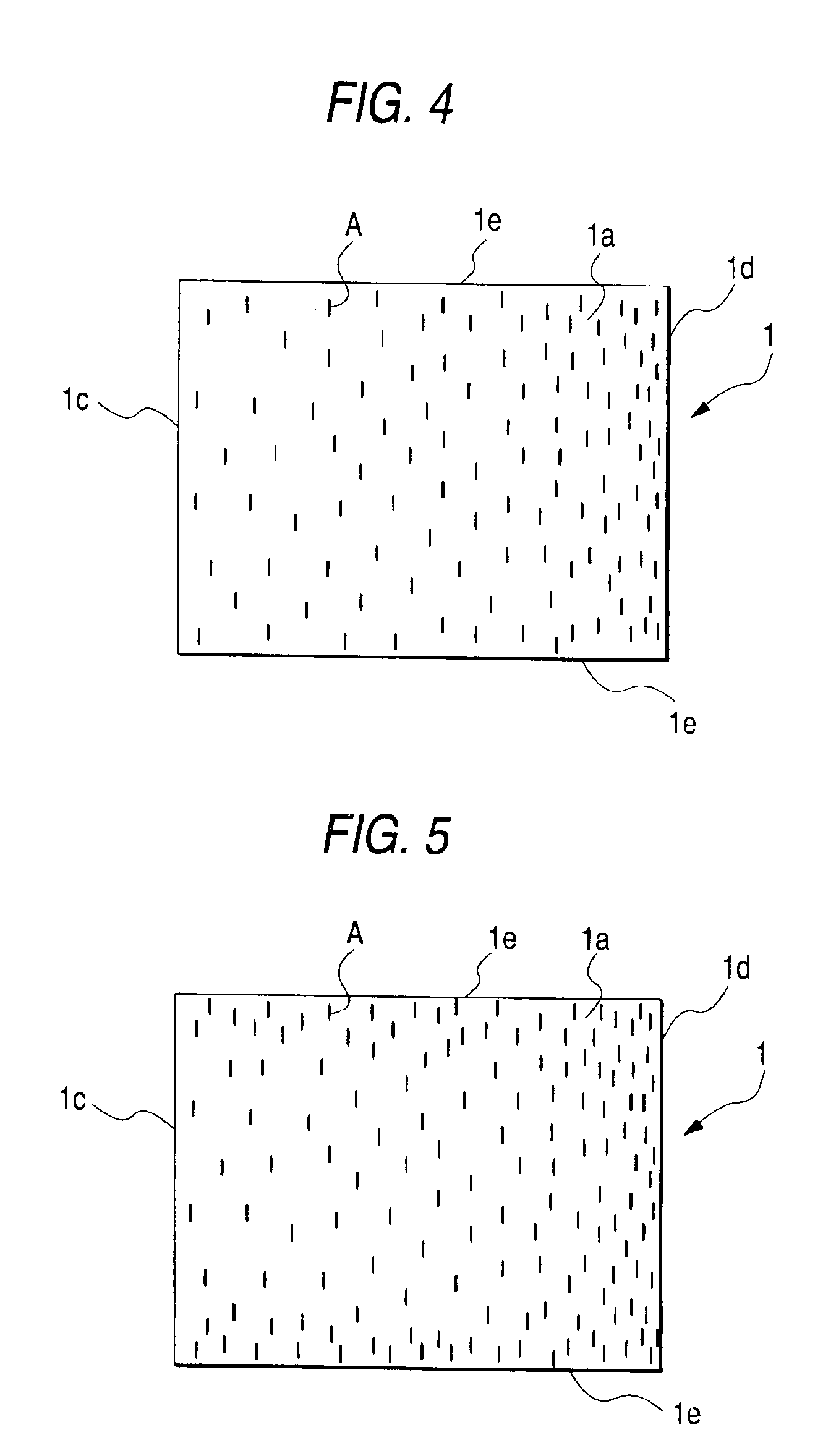
[0082]A chromium mask was formed as follows. Openings each 100 μm long and 10 μm wide were formed in a 35 mm×25 mm rectangular region of a glass substrate so that the direction of short sides of the rectangular region was parallel with the direction of the length of each of the openings. Incidentally, the openings were disposed so at random that the density of the openings increased gradually from one short side of the rectangular region to the other short side thereof, that is, the density of the openings increased continuously in a direction of the long side of the rectangular region (FIG. 4). The area occupied by the openings in total was selected to be not larger than {fraction (1 / 10)} as large as the area of the rectangular region.

[0083]On the other hand, polyimide varnish was applied onto a clean glass plate by spin coating. After pre-baked at 100° C. for 30 minutes, the polyimide varnish was sintered at 350° C. for 4 hours. Thus, a polyimide coating film 10 μm thick was forme...

reference example 2

[0085]A mold B was obtained in the same manner as in Reference Example 1 except that the sample plate was replaced by a sample plate (FIG. 5) having openings disposed in a rectangular region at random so that the density of arrangement of the openings increased continuously in a direction of each long side of the rectangular region and so that the density in portions nearer to each long side became higher than the density in the center portion of the rectangular region.

reference example 3

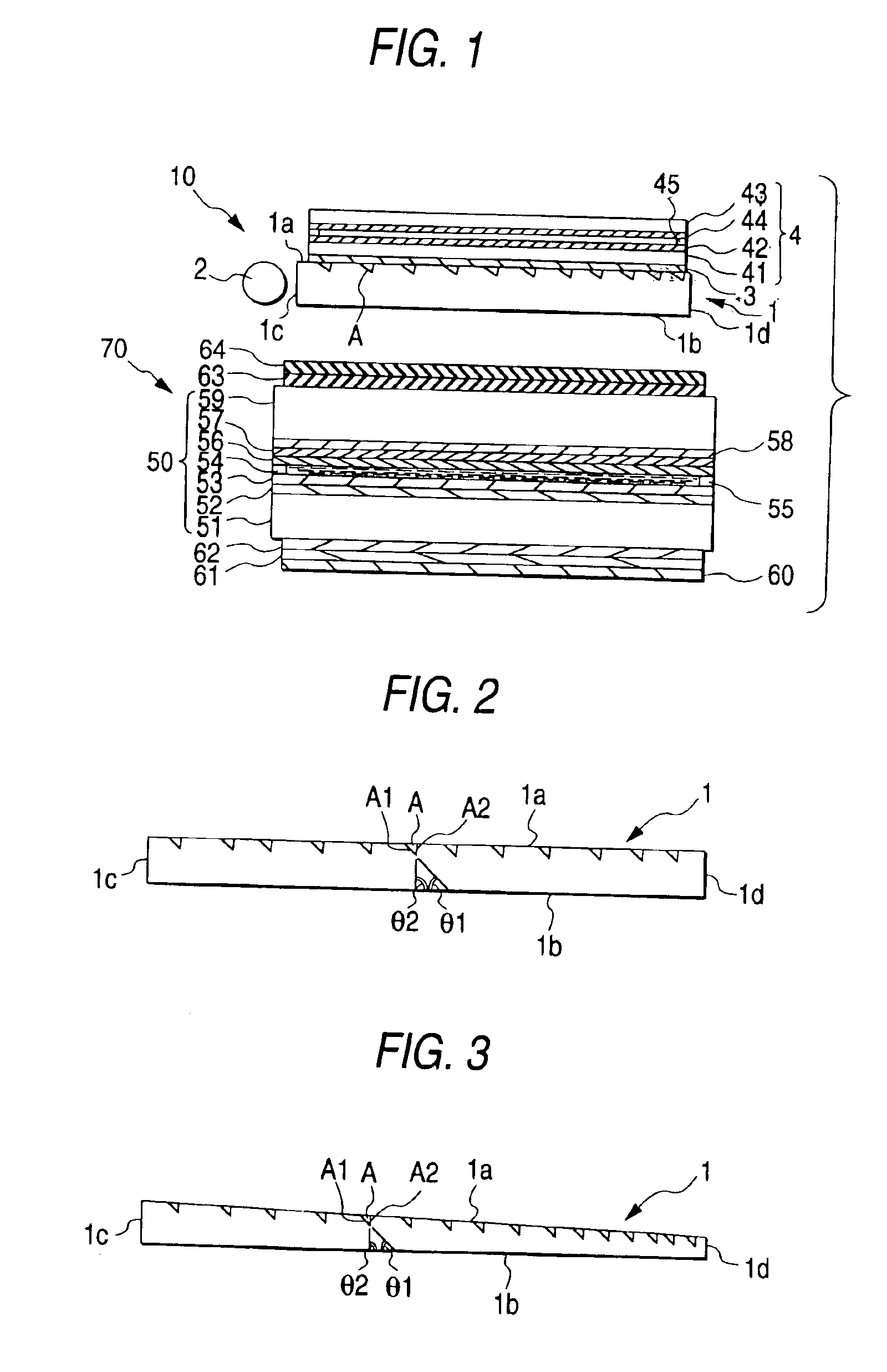
[0086]A surface of a rectangular brass plate was cut at a position far by 2.5 mm from the incidence side surface by a diamond tool. Thus, there was obtained a mold C having striped light output means disposed at intervals of 210 μm and each shaped like a scalene triangle in section. The direction of cutting was selected to be parallel to the direction of the length of the brass plate. Each of the light output means had an optical path changing slope 20 μm wide and inclined at an angle of 42 degrees, and a gentle slope 190 μm wide. The optical path changing slopes faced the incidence side surface. The area occupied by the optical path changing slopes was selected to be {fraction (1 / 10.5)} as large as the area of the upper surface.


PUM

PropertyMeasurementUnit
depthaaaaaaaaaa
depthaaaaaaaaaa
angleaaaaaaaaaa

Abstract

A touch panel-including illuminator having: a light pipe made of a transparent plate-like material having an upper surface, a lower surface and at least one incidence side surface, the upper surface being provided with light output means through which light incident on the incidence side surface is made to emerge from the lower surface; a light source disposed on the incidence side surface of the light pipe; an adhesive layer; and a touch panel bonded to the upper surface of the light pipe through the adhesive layer; wherein the light output means are constituted by fine grooves which are disposed discontinuously, each of which is made of a concave portion, and each of which is shaped like an approximate triangle in section; and wherein each of the fine grooves has an optical path changing slope and a steep slope.

Description

[0001]The present application is based on Japanese Patent Application No. 2001-116430, which is incorporated herein by reference.BACKGROUND OF THE INVENTION[0002]1. Field of the Invention[0003]The present invention relates to a front light type touch panel-including illuminator which can be used for forming a touch-input type reflective liquid-crystal display device displaying an image hardly disordered, free from moire, bright and easy to view.[0004]2. Description of the Related Art[0005]As a related-art reflective liquid-crystal display device having a reflective liquid-crystal display panel, an illuminator constituted by a side light type light pipe, and an input position detecting touch panel provided on a visual side of the reflective liquid-crystal display panel through the illuminator, there is known a reflective liquid-crystal display device having a touch panel-including illuminator formed by integrating a touch panel with a side light type light pipe, the touch panel inclu...

Claims


Application Information

Patent Timeline
10 May 2005
Publication
US6891530B2
IPC
G06F3/033; G02B6/00; F21V8/00; F21Y103/00; G02F1/133; G02F1/1333; G02F1/1335; G02F1/13357; G06F3/041; G09F9/00
CPC
G02B6/0036; G06F3/041; G02F1/13338; G02B6/0061; G06F3/045; G02F1/1335
Inventors
UMEMOTO, SEIJI; KINOSHITA, RYOJI