Laser driver with noise reduction feedback for optical storage applications

a technology of optical storage and laser driver, which is applied in the direction of semiconductor lasers, laser details, electrical apparatus, etc., can solve the problems of affecting the density achievable on the storage media, affecting the integrity of data, and limiting the density of optics and lasers, so as to minimize the noise created by the laser driver circuit itself, the noise reduction effect is also minimized

Inactive Publication Date: 2005-05-10
ALLIANCE STORAGE TECH
View PDF34 Cites 17 Cited by
  • Summary
  • Abstract
  • Description
  • Claims
  • Application Information

AI Technical Summary

Benefits of technology

[0028]It is an additional object of the present invention to provide selective noise reduction such that the write operations are not affected. To achieve this, it is desirable to utilize a switched feedback network that can be selectively disabled.
[0029]It is yet another object of the present invention to provide noise reduction directly to the laser it

Problems solved by technology

Thus, data points can potentially be placed too close together, resulting in meaningless information.
Obviously, the optics and lasers have limits which affect the density achievable on the storage media.
If the density is excessively increased, the integrity of the data will be compromised.
Again, this results in unusable, inefficient data storage devices.
However, these new lasers appear to generate more noise than previous lasers (e.g., red lasers operating at approximately 650 nm wavelength).
With the newer lasers and tighter data d

Method used


Image

  • Laser driver with noise reduction feedback for optical storage applications
  • Laser driver with noise reduction feedback for optical storage applications
  • Laser driver with noise reduction feedback for optical storage applications

Examples


Embodiment Construction

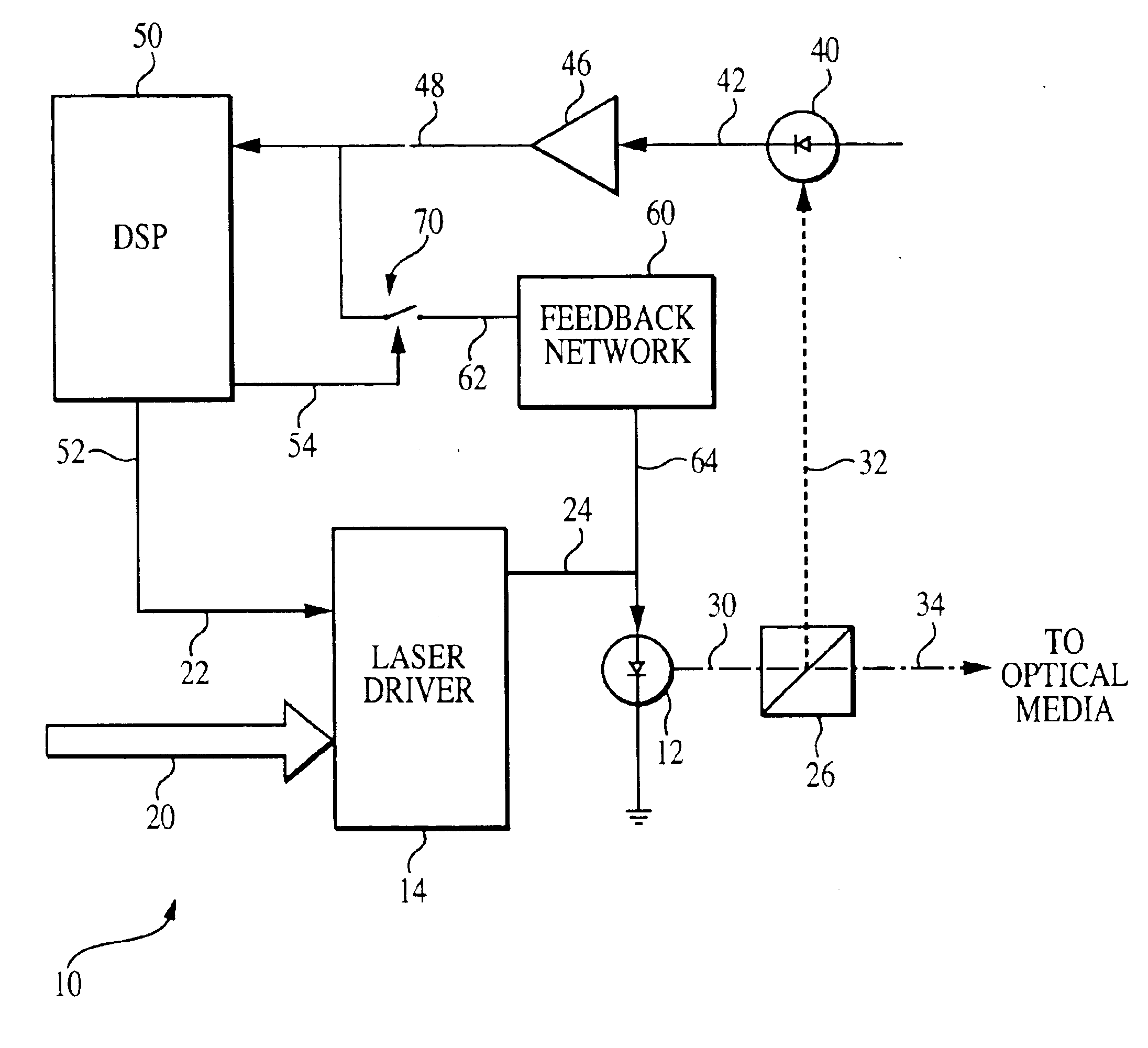
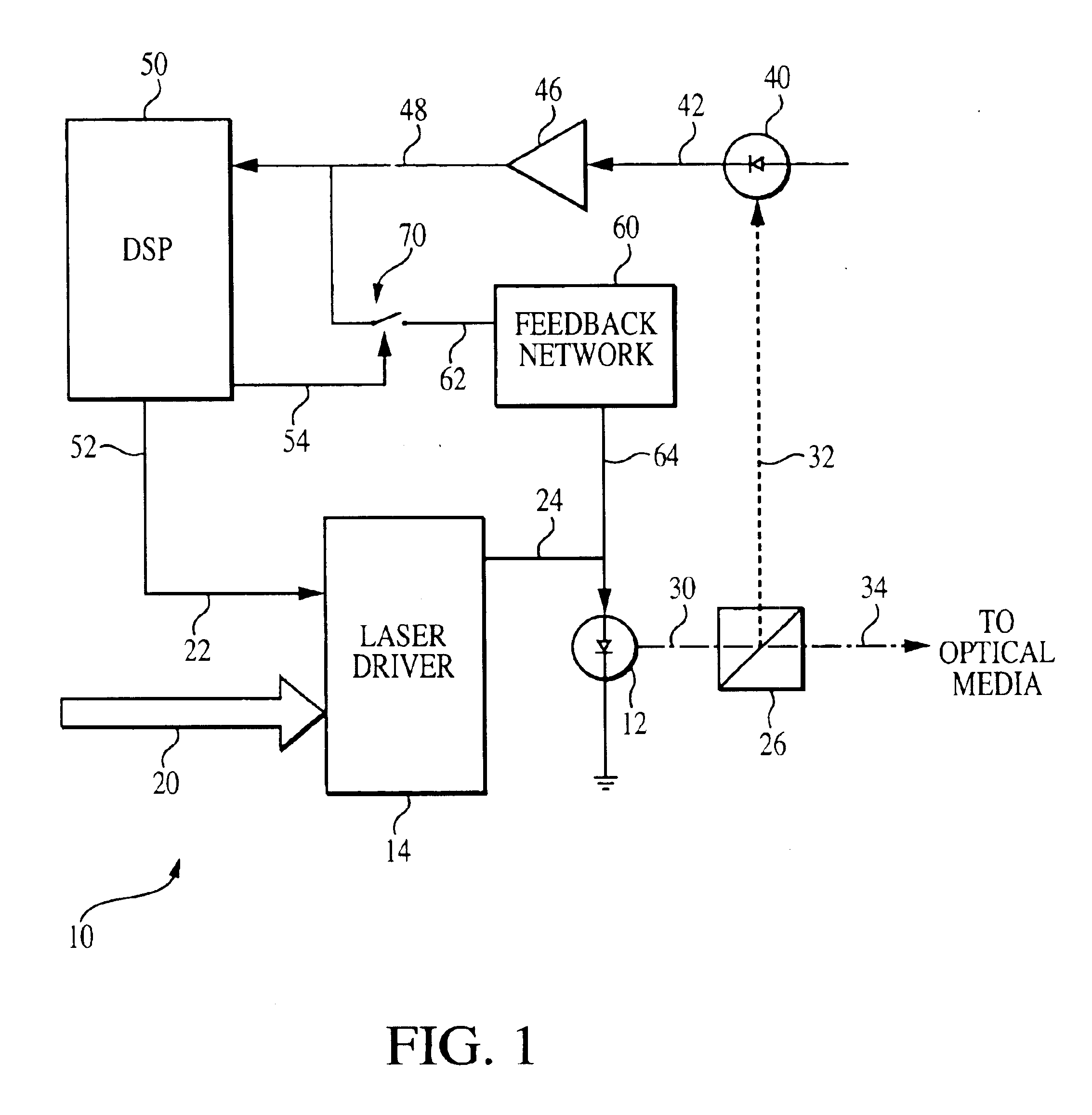
[0038]Referring to FIG. 1, there shown a schematic diagram illustrating the preferred embodiment of the low noise laser control system 10 of the present invention. As described and illustrated below, laser control system 10 is used in an optical data storage system. It is certainly contemplated that this control system 10 could easily be used with other devices that require noise free operation of a laser.

[0039]As with all optical data storage systems, a laser 12 is utilized to generate light signals for reading and writing operations. Laser 12 is controlled by a laser driver 14, which has a write control signal input 20 and a read power input 22. Both of these inputs control the output signal generated at laser driver output 24. Laser driver output 24 is directly attached to laser 14 in order to generate the desired optical signals. The laser driver of the preferred embodiment is a commercially available Elantec EL6287C laser driver manufactured and sold by Elantec Semiconductor, I...


PUM


Abstract

In order to provide a low noise laser beam, a noise reducing feedback network is provided which creates a noise reducing signal and provides that signal to the laser itself. In order to produce the noise reducing signal, the operation of the laser is monitored and the feedback signal is a direct result of this monitoring. Monitoring is accomplished by a fast-forward sense detector, which receives a portion of the laser beam from the operating laser. The output from this fast-forward sense detector is provided to an amplifier which inverts and amplifies the signal. A noise reduction feedback network then receives the amplified signal, appropriately filters this signal, and provides it to the laser itself so as to reduce noise in the laser-beam for the frequency band of importance for reading the recorded data from the optical medium. The noise reduction feedback signal further has sufficiently high impedance so as to not disturb the traditional CW operation of the laser and to avoid interference with the traditional RF modulation of the laser.

Description

BACKGROUND OF THE INVENTION[0001]The present invention relates to optical data storage devices. More specifically, the present invention relates the control and operation of the laser used in optical data storage systems to produce a low noise optical signal for use in reading data from the optical media.[0002]Since the launch in 1982 of the audio CD, optical disks have become a very popular storage media due to their durability, random access features, and the high capacities that can be achieved on a single removable disk. The computerization of businesses has also steadily increased the amount of data that is processed. As more data is processed, the amount of data which must be stored increases as well. To meet the need of this ever-increasing amount of data, cost-effective data storage is desired. To remain competitive and to meet the needs for storage, increasing the disk capacity is a paramount development goal for optical drive products. (See, P. Asthana, B. I. Finkelstein, ...

Claims


Application Information

Patent Timeline
IPC IPC(8): H01S5/0683H01S5/00H01S5/068
CPCH01S5/0683H01S5/06817
Inventor VERBOOM, JOHANNES J.BROOKE, JEFFREY M.KLINE, GARY L.
Owner ALLIANCE STORAGE TECH
Why Eureka
Try Eureka