
Wavelength division multiplex transmission system

a transmission system and wavelength division technology, applied in multiplex communication, instruments, optical elements, etc., can solve the disadvantages of excessive losses, disadvantages of high cost of each transmitting section, and high cost disadvantages, so as to achieve more flexibly stabilize the wavelength

Inactive Publication Date: 2005-05-10
PANASONIC CORP
View PDF7 Cites 1 Cited by
  • Summary
  • Abstract
  • Description
  • Claims
  • Application Information

AI Technical Summary

Benefits of technology

[0013]Therefore, an object of the present invention is to provide a wavelength division multiplex transmission system capable of monitoring and controlling an optical wavelength without newly adding an expensive optical device. Another object of the present invention is to provide a wavelength division multiplex transmission system capable of more flexibly stabilizing the wavelength.
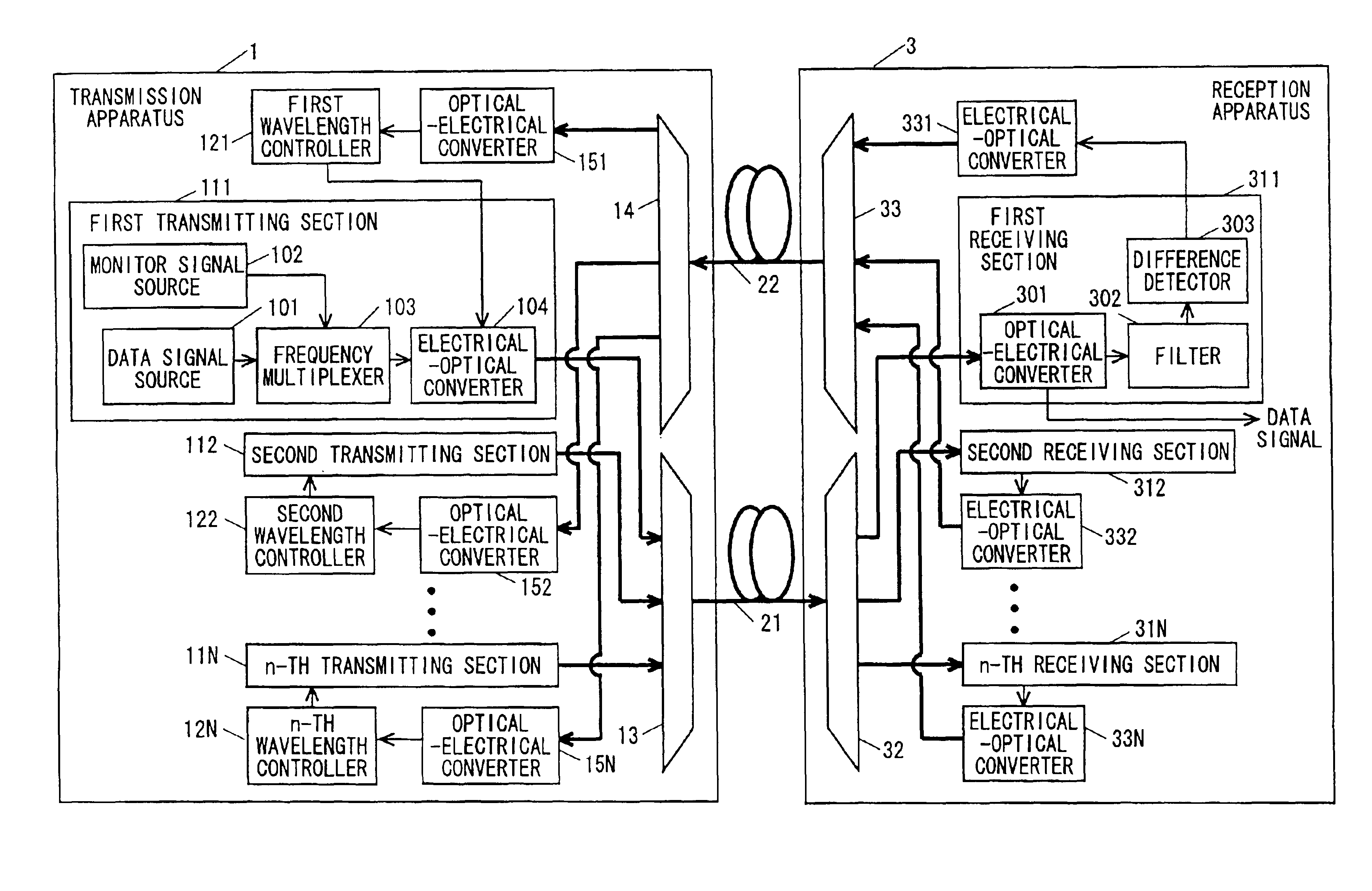
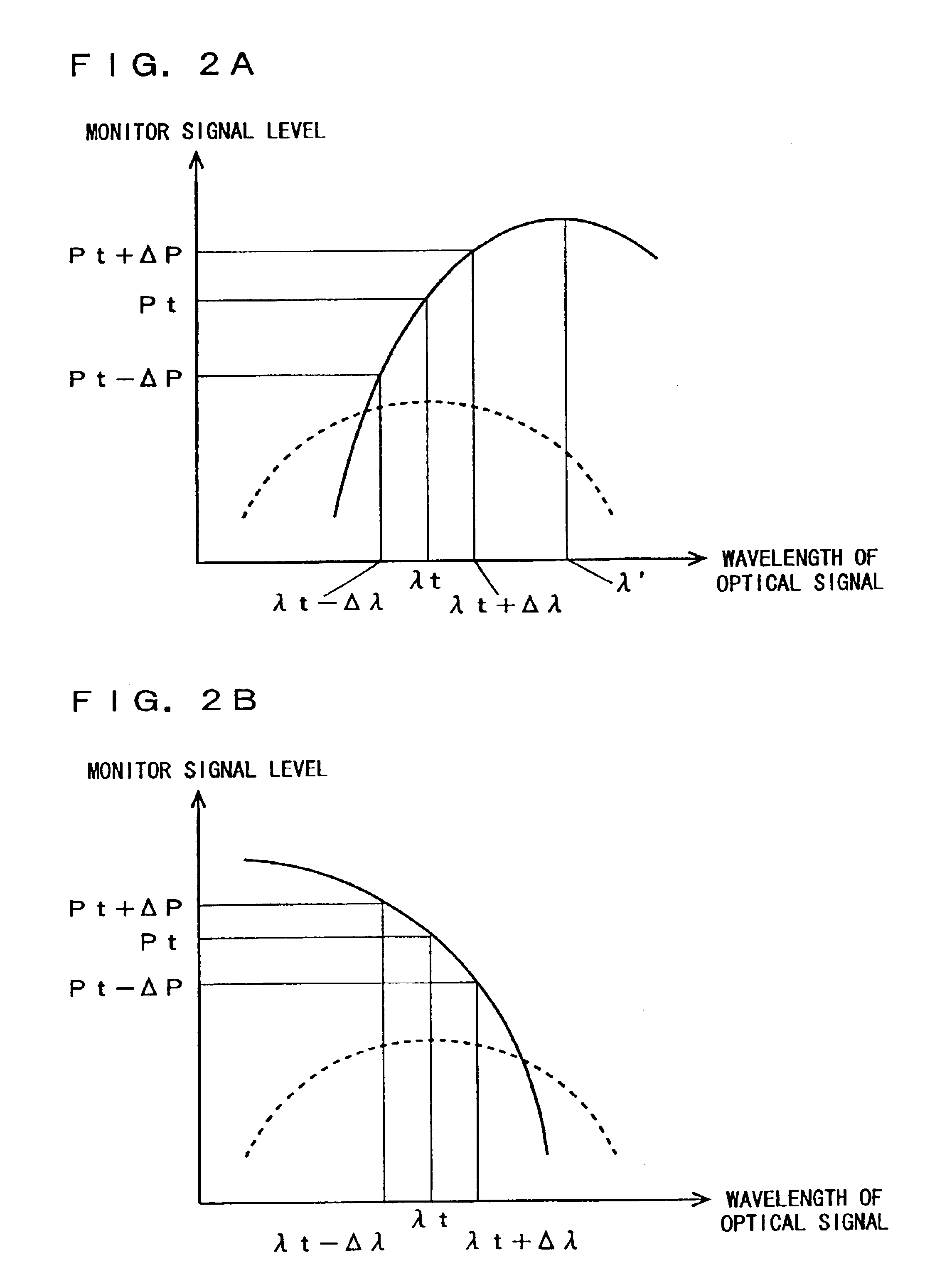
[0015]A system of the present invention is a wavelength division multiplex transmission system in which optical signals of different wavelengths are transmitted by using a wavelength division multiplex scheme, and includes a transmitting section (111, 1101, 2101, 3101), a wavelength multiplexer (13, 53), an optical transmission path (21), a wavelength demultiplexer (32, 65), a control signal generator (303, 105, 62, 79), and a wavelength controller (121). The transmitting section uses an electrical-optical converter (104, 41) for generating an optical signal having therein a monitor signal multiplexed on a data signal to be transmitted and having wavelength chirp due to the monitor signal. The wavelength multiplexer multiplexes the optical signal generated by the transmitting section with another optical signal having a wavelength different from a wavelength of the optical signal. The optical transmission path propagates a multiplexed optical signal obtained by the wavelength multiplexer. The wavelength demultiplexer demultiplexes the optical signal propagated via the optical transmission path, and obtains the optical signal generated by the transmitting section so as to obtain the data signal. The control signal generator generates a control signal based on the monitor signal included in the optical signal after a desired wavelength (λt) is extracted based on a transmission characteristic (dotted lines in FIGS. 2A and 2B) of the wavelength multiplexer or the wavelength demultiplexer. The wavelength controller controls, based on the control signal, a wavelength of light output from the electrical-optical converter. As such, in the wavelength division multiplex transmission system, a wavelength control is performed by using the transmission characteristics of the optical device (the wavelength multiplexer or the wavelength demultiplexer), which are originally required for transmitting a data signal in the system, without requiring an expensive optical device, such as an optical filter, dedicated to the wavelength control. Therefore, it is possible to greatly reduce cost associated with the wavelength control.
[0022]Still further, the difference detector (303) can reset the reference level (Pt). With this, it is possible to flexibly adapt to changes in the environment where the system is located.
[0024]Still further, the transmitting section (1101) may include a polarity inverter (45) for inverting a polarity of the monitor signal for output, and the intensity modulator (47) may intensity-modulate the light output from the electrical-optical converter (41) with a signal having therein a signal output from the polarity inverter multiplexed with the data signal (FIG. 6). With this, it is possible to reduce an intensity-modulated component caused by the monitor signal.
[0026]Still further, a plurality of transmitting sections (111), control signal generators (311), and wavelength controllers (121) may be provided. In this case, the wavelength multiplexer may have a plurality of input terminals each for passing only an optical signal having a predetermined different wavelength and a single output terminal, may wavelength-multiplex optical signals of different wavelengths output from the plurality of said transmitting sections (111 through 11N) and received at the input terminals, and may output an optical signal from the output terminal. Here, the monitor signals each to be multiplexed on the data signal in each of the transmitting sections (111 through 11N) may have different frequencies. Each of the control signal generators (311 through 31N) may extract the intensity-modulated component caused by the monitor signal multiplexed on the data signal at each corresponding transmitting section (111 through 11N), and may generate the control signal based on the extracted intensity modulated component (FIG. 1). With this, all components required for wavelength control can be gathered in the transmitting side, thereby allowing easy maintenance.

Problems solved by technology

For this reason, even if the wavelength of the optical signal is slightly deviated from the transmission center waveform of the waveform demultiplexer, excessive losses disadvantageously occur.
However, these optical devices are generally expensive.
Therefore, extremely high costs are disadvantageously required for each transmitting section.
Furthermore, with these expensive optical devices being required for each transmitting section, cost effectiveness of the entire wavelength division multiplex transmission system is significantly degraded as the size of the system is increased.
In the conventional wavelength division multiplex transmission system, however, such a characteristic of the wavelength demultiplexer is not considered by the wavelength controller.
Therefore, the conventional system does not have any means for improving and stabilizing signal transmission characteristics having degraded by changes in the transmission characteristics of the wavelength demultiplexer.
For this reason, it is difficult to mitigate degradation of the signal transmission characteristics in the wavelength division multiplex transmission system.

Method used


Image

  • Wavelength division multiplex transmission system
  • Wavelength division multiplex transmission system
  • Wavelength division multiplex transmission system

Examples


first embodiment

[0056](First Embodiment)

[0057]A wavelength division multiplex transmission system according to a first embodiment of the present invention is described below. FIG. 1 is a block diagram illustrating the configuration of a wavelength division multiplex transmission system according to the present invention. In FIG. 1, the wavelength division multiplex transmission system includes a transmission apparatus 1, first and second optical transmission paths 21 and 22 typified by optical fibers, and a reception apparatus 3. The transmission apparatus 1 includes first through N-th transmitting sections 111 through 11N, first through N-th wavelength control sections 121 through 12N, a wavelength multiplexer 13, a wavelength demultiplexer 14, and N optical-electrical converters 151 through 15N. The reception apparatus 3 includes first through N-th receiving sections 311 through 31N, a wavelength demultiplexer 32, N electrical-optical converters 331 through 33N, and a wavelength multiplexer 33.

[0...

second embodiment

[0076](Second Embodiment)

[0077]Next, a wavelength division multiplex transmission system according to a second embodiment is described below. FIG. 5 is a block diagram illustrating the configuration of the wavelength division multiplex transmission system according to the second embodiment. In FIG. 5, components similar in operation to those according to the first embodiment are provided with the same reference numerals, and are briefly described herein.

[0078]InFIG. 5, the wavelength division multiplex transmission system includes the transmission apparatus 1, the first and second optical transmission paths 21 and 22, and the reception apparatus 3. The transmission apparatus 1 includes the first through N-th transmitting sections 111 through 11N, first through N-th wavelength adjusters 161 through 16N, the wavelength multiplexer 13, the wavelength demultiplexer 14, and the N optical-electrical converters 151 through 15N. The reception apparatus 3 includes first through N-th receivin...

third embodiment

[0087](Third Embodiment)

[0088]FIG. 6 is a block diagram illustrating the configuration of a wavelength division multiplex transmission system according to a third embodiment of the present invention. The wavelength division multiplex transmission system includes N transmitting sections 1101 through 110N, a wavelength multiplexer 13, an optical transmission path 21, a wavelength demultiplexer 32, and N receiving sections 1301 through 130N. The transmitting section 1101 includes a semiconductor laser 41, a wavelength controller 121, a monitor signal source 102, a current source 44, a polarity inverter 45, a multiplexer 46, and an intensity modulator 47. The receiving section 1301 includes an optical-electrical converter 301 and a control signal generator 62.

[0089]With reference to FIG. 6, the function of each component according to the present embodiment is described below.

[0090]The semiconductor laser 41 outputs light. The wavelength controller 121 controls a center wavelength λ0 of ...


PUM


Abstract

A first transmitting section frequency-multiplexes a data signal and a monitor signal, and then converts the resultant signal to an optical signal for output. A first receiving section converts the optical signal transmitted via a first optical transmission path and a wavelength demultiplexer into an electrical signal, and then extracts the monitor signal. A difference detector compares a monitor signal level with a predetermined reference level, and then outputs wavelength information to a second optical transmission path. Based on the wavelength information transmitted via the second optical transmission path, a first wavelength controller adjusts the wavelength of the optical signal for stabilization at a predetermined wavelength. Thus, it is possible to achieve a wavelength division multiplex transmission system capable of controlling the wavelength of the optical signal at low cost.

Description

BACKGROUND OF THE INVENTION[0001]1. Field of the Invention[0002]The present invention relates to wavelength division multiplex transmission systems for transmitting optical signals having different wavelengths by using a wavelength division multiplex technology.[0003]2. Description of the Background Art[0004]In recent years, in order to cope with an increase in demand for large-volume data, a high-density wavelength division multiplex transmission system (hereinafter referred to as a DWDM system) has been rapidly widespread.[0005]In the DWDM system, a plurality of optical signals are transmitted with their wavelengths aligned at narrow intervals of 1 nm or less. Therefore, transmission characteristics of a wavelength demultiplexer for demultiplexing and extracting the optical signals have to be steeply attenuated outside a desired wavelength band. For this reason, even if the wavelength of the optical signal is slightly deviated from the transmission center waveform of the waveform ...

Claims


Application Information

Patent Timeline
Patent Type & Authority Patents(United States)
IPC IPC(8): H04B10/08H04B10/02H04J14/02
CPCH04B10/00H04J14/0221H04B2210/078
Inventor IKUSHIMA, TSUYOSHIFUSE, MASARUYASUE, TOSHIHIKO
Owner PANASONIC CORP
Learn More