Method and apparatus for modeling mass storage disk drive motors

a disk drive and mass storage technology, applied in the direction of dynamo-electric converter control, instruments, analogue processes for specific applications, etc., can solve the problems of increasing phase inductance, and achieve the effects of increasing control accuracy, high current, and high speed

Inactive Publication Date: 2005-05-10
TEXAS INSTR INC
View PDF15 Cites 9 Cited by
  • Summary
  • Abstract
  • Description
  • Claims
  • Application Information

AI Technical Summary

Benefits of technology

[0010]The present invention provides an improved model and methodology for simulating motor performance which allows increased control accuracy at the high current, high speed, and / or high current change rates and data densities required in modem mass storage devices. In order to increase the storage capacity of hard disk drive devices, the number of platters may be increased, which requires higher startup current capability. In addition, motors designed for higher current operation typically have decreased phase resistances, resulting in increased phase inductance. Storage capacity may also be increased by increasing the data density or TPI of the platters. Corresponding improvement in spindle motor speed control accuracy is needed to accommodate the increased data density. Whereas prior motor modeling and simulation was sufficient for disk drive spindle motors operating at current speeds and data densities, the invention provides improved accuracy to enable high current, high speed, and / or high current change rate operation in association with higher data density drives. The invention provides a model for an electric motor which allows motor behavior or performance to be accurately analyzed, and a load circuit for simulating motor performance. In addition, the invention provides methods for simulating motor performance, and for testing a motor commutation scheme.
[0011]According to one aspect of the present invention, there is provided a model for simulating the performance of a polyphase electric motor. The model includes a plurality of phases extending between first ends joined at a center tap and second ends extending outward from the center tap to a corresponding plurality of phase taps, and a mutual inductance component disposed between two of the phases. The model may be used to simulate the performance of a motor, and finds particular utility in high current, high speed, and / or high current change rate motor control applications. The mutual inductance component may be a function of rotor position, thereby providing for improved control accuracy. In addition, at least one phase of the motor model may comprise a phase resistance component, a back emf component, and a phase inductance component, where the phase inductance component and / or the back emf component may also be a function of rotor position.
[0013]According to yet another aspect of the invention, there is provided a method of simulating the performance of a motor which facilitates development of high accuracy commutation control circuits and schemes for controlling high speed disk drive spindle motors for use in high density storage devices. The method employs a motor model having plurality of phases extending between first ends joined at a center tap and second ends extending outward from the center tap to a corresponding plurality of phase taps, and a mutual inductance component disposed between two of the phases. The method further includes applying an input signal to at least one of the phase taps, simulating the performance of a motor using the model and the input signal, and observing the performance of the model.
[0014]According to another aspect of the invention, the method may employ a three phase motor model having three phases and a center tap, with phase to phase mutual inductance components disposed there between, wherein input signals are applied to at least one of the phase taps. The performance of the motor is then simulated using the model and the input signals, and the motor performance is then observed. The motor model may include one or more components or elements which are a function of rotor position, allowing for improved motor position and speed control simulation, particularly at high rotor speeds. In this regard, the mutual inductance components may be a function of rotor position. The application of input signals to the phase taps may comprise providing commutation signals according to a commutation scheme, and observing the performance of the model may include determining the rotor position as a function of time.

Problems solved by technology

In addition, motors designed for higher current operation typically have decreased phase resistances, resulting in increased phase inductance.

Method used


Image

  • Method and apparatus for modeling mass storage disk drive motors
  • Method and apparatus for modeling mass storage disk drive motors
  • Method and apparatus for modeling mass storage disk drive motors

Examples


Embodiment Construction

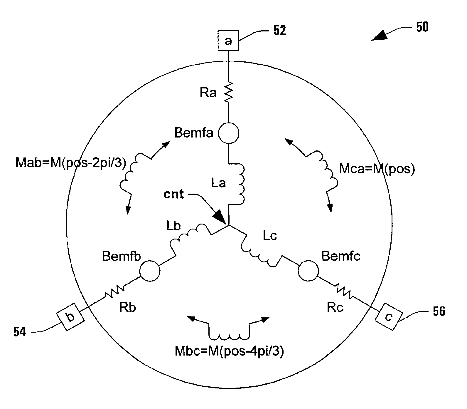
[0032]The present invention will now be described with respect to the accompanying drawings in which like numbered elements represent like parts. The invention is directed to a model for an electric motor finding particular application in simulating the performance of a high speed mass storage device spindle motor. The model includes components heretofore not found in conventional motor models which provide for improved simulation accuracy in high speed motor applications such as hard disk drive spindle motors. In particular, the invention includes one or more mutual inductance components in a polyphase motor model which may be a function of rotor position. The invention further includes a load circuit and methods for simulating motor performance and for testing a motor commutation scheme. While the various aspects of the invention are illustrated hereinafter with respect to certain motor winding configurations, it will be appreciated that the invention finds applications in associa...


PUM


Abstract

The present invention provides an improved model and methodology for simulating motor performance which allow increased control accuracy at the higher currents, higher speeds, and / or higher current change rates required in modem mass storage devices. In addition, the invention provides methods for simulating motor performance, and for testing a motor commutation scheme. The model includes a plurality of phases extending between first ends joined at a center tap and second ends extending outward from the center tap to a corresponding plurality of phase taps, and a mutual inductance component disposed between two of the phases, wherein the mutual inductance and / or the phase inductance components may be a function of rotor position and / or current.

Description

TECHNICAL FIELD[0001]This invention relates generally to the field of electric motor driving systems, and more particularly to a method and apparatus for modeling mass storage disk drive motors.BACKGROUND OF THE INVENTION[0002]Electric motors include a rotor and a stator having a plurality of wound field coils. Brushless DC motors are electronically commutated, wherein solid-state switching replaces the brushes and segmented commutators of traditional permanent magnet DC motors. Brushless motors may be of the variable reluctance, permanent magnet, or hybrid type. Variable reluctance brushless motors are characterized by having an iron core rotor follow or chase sequentially shifting magnetic fields of the stator coils to facilitate rotational motion of the rotor. Permanent magnet brushless motors are characterized by having the sequentially energized field coils attract or repel a permanent magnet rotor into rotational motion.[0003]Electric motors are used to rotate loads in a varie...

Claims


Application Information

Patent Timeline
Patent Type & Authority Patents(United States)
IPC IPC(8): G06G7/62G06G7/00H02P6/00
CPCH02P6/001H02P6/34
Inventor DU, TANWHYTE, JR., ROBERT E.
Owner TEXAS INSTR INC
Why Eureka
Try Eureka