Surround for speaker system and manufacturing method thereof

a speaker system and surround technology, applied in the field of surrounds, can solve the problems of large vibration amplitude of the diaphragm and high pressure inside the speaker enclosure, insufficient rigidity of the conventional speaker surround, and inability to withstand large vibration, etc., and achieve the effect of high sound pressure and high durability

Inactive Publication Date: 2005-05-17
PIONEER CORP +1
View PDF19 Cites 18 Cited by
  • Summary
  • Abstract
  • Description
  • Claims
  • Application Information

AI Technical Summary

Benefits of technology

[0009]The present invention has been devised under the circumstances described above, its object being to provide a speaker's surround which is capable of keeping its predetermined shape while repeating elastic deformation for accommodating large amplitude vibration of the diaphragm, which is highly durable to withstand the repeated large amplitude vibration, and which can achieve high sound pressure levels, and a manufacturing method thereof.

Problems solved by technology

In a high-power, high-output speaker system such as a subwoofer speaker system, a malfunction or breakage sometimes occurs in the surround, resulting from the large vibration amplitude of the diaphragm and the high pressure inside the speaker enclosure.
This is because the conventional speaker's surround has a rigidity which is insufficient for the high-power, high-output speaker system.
The diaphragm then moves irregularly and intrinsic resonance occurs in the surround, resulting in distortion at low sound levels and noises.
If the surround is made of a urethane foam material, it may eventually break, because the material cannot withstand repeated vibration with a large amplitude in the high-power, high-output speaker system.
The rigidity of the speaker's surround could be increased simply by making the material thickness larger, but this will increase its weight and lower the speaker efficiency, and high sound pressure levels can not be achieved.

Method used


Image

  • Surround for speaker system and manufacturing method thereof
  • Surround for speaker system and manufacturing method thereof
  • Surround for speaker system and manufacturing method thereof

Examples


Embodiment Construction

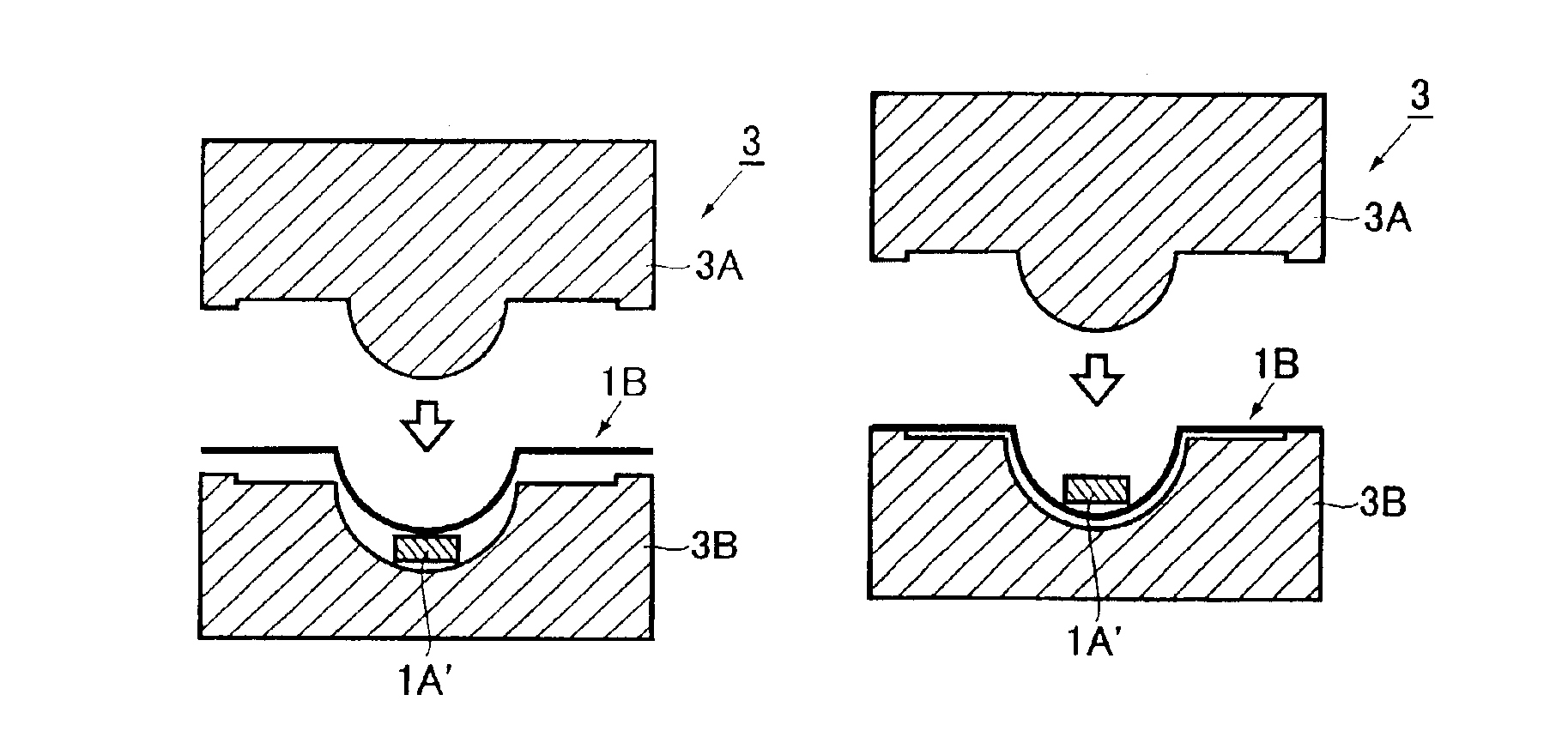
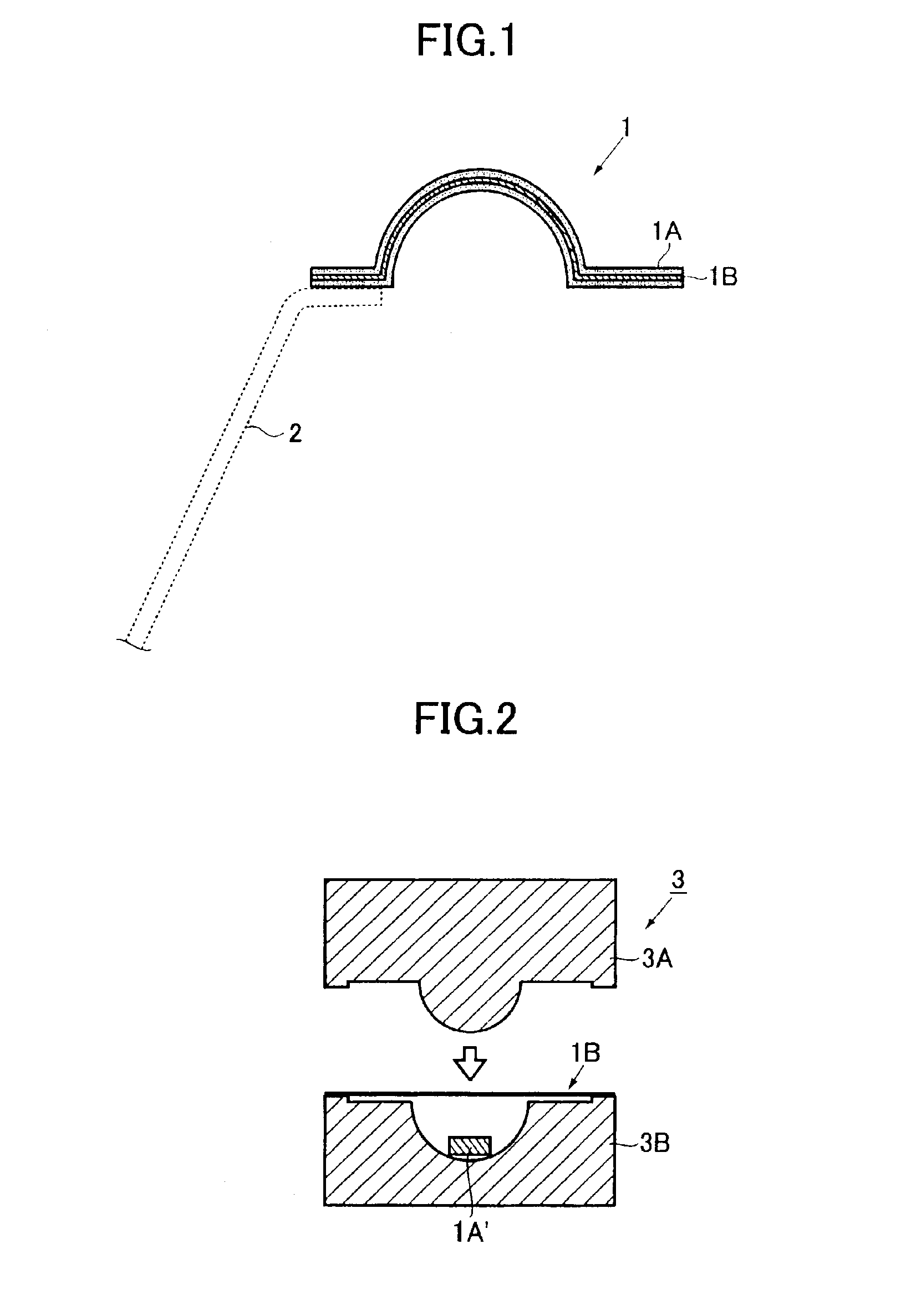
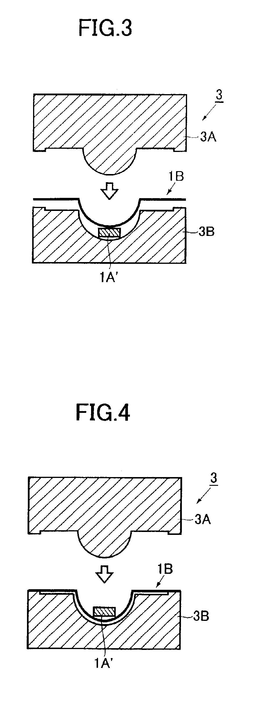
[0033]Preferred embodiments of the present invention will be hereinafter described with reference to the accompanying drawings. FIG. 1 is a cross section of a surround used in a speaker system. The surround 1 comprises a surround piece 1A and a base member 1B arranged in the surround piece 1A, and is formed in a rolled shape protruding to the front side. The surround 1 is provided to an outer edge of a cone diaphragm 2 shown by broken lines for flexibly supporting the cone diaphragm 2 on a speaker frame (not shown).

[0034]The surround piece 1A is formed by molding a rubber material containing as its main component at least one member selected from the group consisting of isobutylene isoprene rubber (IIR), acrylonitrile butadiene rubber (NBR), styrene butadiene rubber (SBR), ethylene propylene diene monomer rubber (EPDM), chloroprene rubber, isoprene rubber, ethylene propylene rubber, polynorbornene rubber, silicone rubber, epichlorohydrin rubber, and natural rubber. The base member 1...


PUM

PropertyMeasurementUnit
temperatureaaaaaaaaaa
heataaaaaaaaaa
pressureaaaaaaaaaa

Abstract

A speaker's surround to be attached to an edge of a diaphragm in a speaker system is provided, which is capable of keeping its predetermined shape while repeating elastic deformation for accommodating large amplitude vibration of the diaphragm. Further, the surround is highly durable to withstand the repeated large amplitude vibration, and which can achieve high sound pressure levels. The surround for a speaker system includes a surround piece made of a rubber mold and a base member embedded in the surround piece. The base member is obtained by soaking a cloth material made of cotton or aramid fiber with a thermosetting resin such as phenol resin, and press-formed with heat into a predetermined shape. The surround thus has enhanced its shape maintaining capability.

Description

BACKGROUND OF THE INVENTION[0001]The present invention relates to a surround to be attached to the edge of a diaphragm of a speaker system, and a manufacturing method thereof.[0002]The present application claims priority from Japanese Application Nos. 2002-098131 and 2002-290640, the disclosure of which is incorporated herein by reference.[0003]Surround is a speaker component fitted to an outer peripheral edge of a diaphragm for flexibly supporting the diaphragm on a speaker frame. It is for holding the diaphragm in place and should satisfy the following requirements: an ability (linearity) to move the periphery of the diaphragm linearly when a driving force is applied to the diaphragm, an ability to suppress lateral vibration of the diaphragm, and good air tightness so that sound waves reflected by the backside of the diaphragm are not released to the front side thereof. It is also important that no intrinsic resonance occurs in the surround itself when it vibrates by the actuation...

Claims


Application Information

Patent Timeline
Patent Type & Authority Patents(United States)
IPC IPC(8): H04R7/00H04R7/20H04R31/00
CPCH04R7/20H04R31/00Y10T29/49005H04R2307/204Y10T29/4908H04R2231/003
Inventor SUZUKI, TAKASHISATO, MASATOSHI
Owner PIONEER CORP
Why Eureka
Try Eureka