Microsensors for glucose and insulin monitoring

a glucose and insulin monitoring and microsensor technology, applied in the field of microsensors for glucose and insulin monitoring, can solve the problem of not providing simultaneous detection of glucose and insulin, and achieve the effect of reducing interference and increasing accuracy and selectivity

Inactive Publication Date: 2005-05-17
ARROWHEAD CENT
View PDF40 Cites 485 Cited by
  • Summary
  • Abstract
  • Description
  • Claims
  • Application Information

AI Technical Summary

Benefits of technology

[0027]A primary advantage of the present invention is that it provides for simultaneous measurement of both glucose and insulin, utilizing different but compatible transduction principles.
[0028]Another advantage of the present invention is that it provides a miniature, needle-type dual sensor that may be employed as an implantable sensor.
[0029]Another advantage is the lack of need for an exogenous oxygen source or supply.
[0030]Another advantage of the present invention is the increased accuracy and selectivity due to lessened interferen...

Problems solved by technology

However, this approach does not provide for simultaneous detec...

Method used


Image

  • Microsensors for glucose and insulin monitoring
  • Microsensors for glucose and insulin monitoring
  • Microsensors for glucose and insulin monitoring

Examples


example 1

[0060]Cyclic voltammetry was conducted using a modular electrochemical system, with flow injection amperometric data collected using voltammetric analyzers with recorders. A standard flow injection system was utilized. Currents were measured in two electrode systems, with stainless steel and Ag / AgCl serving as reference electrodes for glucose and insulin measurements, respectively. Voltages are against the relevant reference electrode.

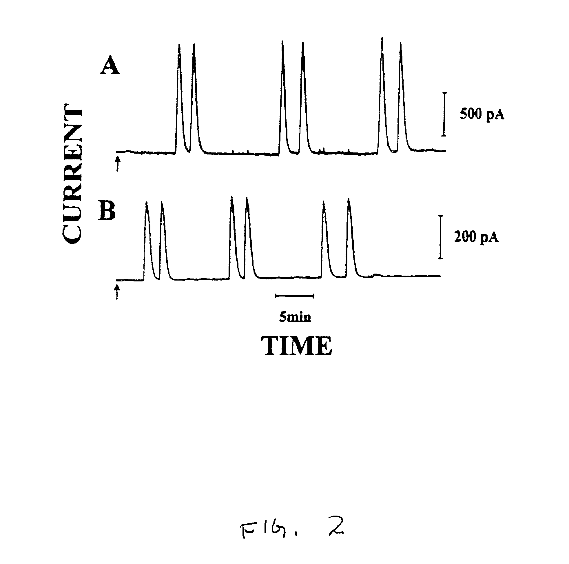
[0061]FIG. 2 depicts dual channel flow injection current and time profiles at the needle detector of FIG. 1 for alternating injections of 5 mM glucose (A) and 400 nM insulin (B). The applied potential for both sensors was +0.6 V against stainless steel, for the glucose sensor, and against Ag / AgCl, for the insulin sensor. The carrier solution was 0.1 M NaCl and 0.05 M phosphate buffer at pH 7.4, with a flow rate of 0.5 mL per minute. Both glucose sensor 36 and insulin sensor 40 responded rapidly to injections of the target analytes, with nearly instanta...

example 2

[0062]The concentration of RuOx and plating time in the electrochemical deposition were determined. Insulin response increased rapidly with the RuOx plating time up to a plating time of about ten minutes, and leveled off at a plating time of about above twenty minutes. The effect of detection potential was also determined. Insulin anodic response started at +0.3 V, rose sharply to about +0.55 V, and leveled off at higher values. Reported data was obtained utilizing a 25 minute RuOx plating time and a detection potential of +0.6 V.

example 3

[0063]FIG. 3 shows the simultaneous response to glucose (A) and insulin (B) in mixtures containing varying concentrations of glucose and a fixed concentration of insulin. Operating conditions were as described for Example 1. The glucose signal increased linearly with the concentration over a 3 to 7 mM range, without influencing response for the 200 nM insulin. Additionally, both glucose and insulin signals, for a series of twelve repetitive injections, were highly consistent, demonstrating reproducibility. The mean peak current for glucose peaks (A) was 860 pA and a relative standard deviation of 2.6%, and for insulin peaks (B) was 243 pA, with a relative standard deviation of 4.1%.


PUM

PropertyMeasurementUnit
Diameteraaaaaaaaaa
Diameteraaaaaaaaaa
Diameteraaaaaaaaaa

Abstract

A dual sensor for the simultaneous amperometric monitoring of glucose and insulin, wherein the glucose probe is based on the biocatalytic action of glucose oxidase, and the insulin probe is based on the electrocatalytic activity of metal oxide. Further provided is an oxidase enzyme composite electrode with an internal oxygen-rich binder. The present invention also optionally includes metallizing components within the carbon paste to eliminate signals from interfering compounds. The present invention includes embodiments for both in vitro and in vivo uses.

Description

CROSS-REFERENCE TO RELATED APPLICATIONS[0001]This application is a continuation-in-part application of U.S. patent application Ser. No. 09 / 216,353, now abandoned entitled Oxygen-Rich Oxidase Enzyme Electrodes, to Joseph Wang and Fang Lu, filed on Dec. 18, 1998, and the specification thereof is incorporated herein by reference. This application claims the benefit of the filing of U.S. Provisional Patent Application Ser. No. 60 / 267,811, entitled Needle-Type Dual Microsensor for the Simultaneous Monitoring of Glucose and Oxygen, filed on Feb. 8, 2001, and of U.S. Provisional Patent Application Ser. No. 60 / 068,916, entitled Oxygen-rich Oxidase Enzyme Electrodes, filed on Dec. 29, 1997, and the specifications thereof are incorporated herein by reference.STATEMENT REGARDING FEDERALLY SPONSORED RESEARCH OR DEVELOPMENT[0002]The U.S. Government has a paid-up license in this invention and the right in limited circumstances to require the patent owner to license others on reasonable terms as p...

Claims


Application Information

Patent Timeline
IPC IPC(8): G01N27/327G01N33/487
CPCG01N27/3271
Inventor WANG, JOSEPHZHANG, XUEJILU, FANG
Owner ARROWHEAD CENT
Why Eureka
Try Eureka