
Solid oxide fuel cell

a fuel cell and solid oxide technology, applied in the direction of cell components, final product manufacturing, sustainable manufacturing/processing, etc., can solve the problems of difficult to obtain a sufficient electrochemical reaction field to occur a cell reaction, difficult to meet the foregoing three requirements of conventional single-layer air and fuel electrodes, and difficult to achieve a wide area of three-phase interface with the thick film thickness of the electrode, etc., to achieve high electricity collection performance

Inactive Publication Date: 2005-05-17
NISSAN MOTOR CO LTD
View PDF13 Cites 19 Cited by
  • Summary
  • Abstract
  • Description
  • Claims
  • Application Information

AI Technical Summary

Benefits of technology

[0011]It is difficult for the conventional single-layered air and fuel electrodes to satisfy the foregoing three requirements. This is because to acquire high electricity collecting performance, the film thickness of the electrode must be thickened, however it is difficult to obtain a sufficient electrochemical reaction field to occur a cell reaction, that is, a wide area of the three-phase interface is impossible with the thick film thickness of the electrode.

Problems solved by technology

It is difficult for the conventional single-layered air and fuel electrodes to satisfy the foregoing three requirements.
This is because to acquire high electricity collecting performance, the film thickness of the electrode must be thickened, however it is difficult to obtain a sufficient electrochemical reaction field to occur a cell reaction, that is, a wide area of the three-phase interface is impossible with the thick film thickness of the electrode.
However, when YSZ (yttria-stabilized-zirconia) is used as a solid electrolyte, the LSC reacts with the YSZ at 1000° C. or more, resulting in deterioration of cell performance.

Method used


Image

  • Solid oxide fuel cell
  • Solid oxide fuel cell
  • Solid oxide fuel cell

Examples


first embodiment

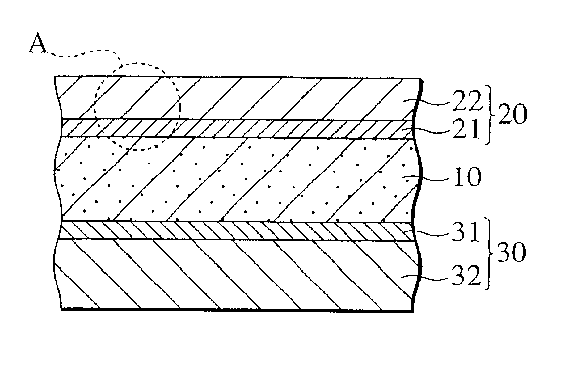
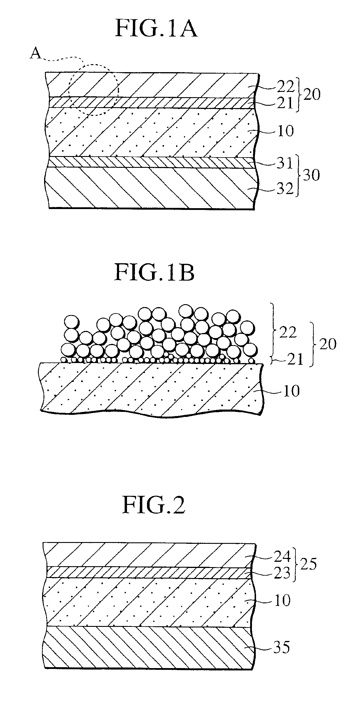
[0029]FIG. 1A shows a structure of a single cell according to a first embodiment of the present invention. Also FIG. 1B shows an enlarged section view of a portion A circled with broken line in FIG. 1A. The single cell has the structure in which the solid electrolyte layer 10 is sandwiched by the air electrode (cathode) 20 and a fuel electrode (anode) 30. The single cell of this embodiment has a feature in that the air electrode 20 and the fuel electrode 30 are respectively formed by at least two layers, each of which has a different function.

[0030]To be concrete, as shown in FIG. 1A, the air electrode 20 has a laminated structure composed of an adhering cathode layer 21 formed on the upper surface of the solid electrolyte layer 10 and an electricity collecting cathode layer 22. The fuel electrode 30 has a laminated structure composed of an adhering anode layer 31 formed on the lower surface of the solid electrolyte layer 10 and an electricity collecting anode layer 32.

[0031]The adh...

second embodiment

[0054]A structure of a single cell according to a second embodiment of the present invention is shown in FIG. 2. Air electrode 25 is formed on one surface of the solid electrolyte layer 10, and a fuel electrode 35 is formed on the other surface thereof. The air electrode 25 have an adhering cathode layer 23 and an electricity collecting cathode layer 24.

[0055]In the single cell of the second embodiment, an ion electron conduction film providing electron conductivity and ion conductivity is used as the adhering cathode layer 23 and the electricity collecting cathode layer 24 of the air electrode 25, and electrode performance of the air electrode 25 is enhanced. Moreover, as the adhering cathode layer 23, silver (Ag), a material essentially containing silver (Ag), bismuth oxide (Bi), or a material essentially containing the bismuth oxide is used.

[0056]Since Ag and bismuth oxide exhibit the electron conductivity and the ion conductivity and have a low melting point, the air electrode c...

examples

[0078]Examples and comparative examples of the present invention will be described below.

[0079]In the examples and the comparative examples described below, the single cell for the fuel cell was fabricated, and performance evaluation for the single cell obtained was performed as described below.

[Performance Evaluation Method]

1. Tape Peeling-off Test Conditions

[0080]Scotch™ tape (manufactured by 3M Co. Ltd., type: Mending Tape 810) was pasted on the surface of the single cell, and the surface of the single cell on which the tape was pasted was pulled with force of 500 g at an angle of 45° relative to the surface of the single cell. When the peeling of the surface of the single cell did not occur, the evaluation was sorted to “◯” (Good).

2. Cell Property Evaluation Conditions

[0081]Cell properties of the fuel cell constituted by use of the single cell of each example were measured under the conditions that temperature was 700° C., fuel gas was hydrogen, oxidation gas was air, and gas pr...


PUM

PropertyMeasurementUnit
particle diameteraaaaaaaaaa
thicknessaaaaaaaaaa

Abstract

A single cell for a fuel cell in which an air electrode or a fuel electrode includes at least two layers. The air electrode includes an adhering cathode layer formed on one surface of the solid electrolyte layer and configured to show a function to allow the air electrode and the solid electrolyte layer to adhere electrically and mechanically to each other, and an electricity collecting cathode layer formed on the adhering cathode layer and configured to show an electricity collecting function of the air electrode. Alternatively, the fuel electrode includes an adhering anode layer formed on the other surface of the solid electrolyte layer and configured to show a function to allow the fuel electrode and the solid electrolyte layer to adhere electrically and mechanically to each other, and an electricity collecting anode layer formed on the adhering anode layer and configured to show an electricity collecting function.

Description

BACKGROUND OF THE INVENTION[0001]1. Field of the Invention[0002]The present invention relates to a solid oxide fuel cell (SOFC) which uses a solid electrolyte to obtain electric energy by utilization of electrochemical reactions.[0003]2. Description of the Related Art[0004]Fuel cells have recently attracted considerable attention as a clean energy source which is capable of high energy conversion and globally environmentally friendly.[0005]A solid oxide fuel cell (hereinafter referred to as “SOFC”) is one having a structure in which two electrodes consisting of an air electrode (cathode) and a fuel electrode (anode) sandwich a solid oxide electrolyte layer. Reactive gas containing oxygen is supplied to the air electrode, and reactive gas containing fuel gas is supplied to the fuel electrode. An electrochemical reaction occurs at a three-phase interface where the electrode, the reactive gas and the solid electrolyte mainly contact. These electrode materials are required to offer the ...

Claims


Application Information

Patent Timeline
Patent Type & Authority Patents(United States)
IPC IPC(8): H01M8/24H01M8/12H01M4/86H01M4/88H01M8/02
CPCH01M4/8642H01M4/8657H01M8/1213H01M8/249H01M8/2425Y02E60/525H01M2008/1293Y02E60/521H01M8/2428H01M8/2432Y02E60/50Y02P70/50
Inventor SHIBATA, ITARUSUGIYAMA, TATSUOHATANO, MASAHARUYAMANAKA, MITSUGUUCHIYAMA, MAKOTOFUKUZAWA, TATSUHIROHARA, NAOKIKUSHIBIKI, KEIKOSATOU, FUMINORI
Owner NISSAN MOTOR CO LTD
Learn More