Gene detection system, gene detection device comprising same, detection method, and gene detecting chip

Inactive Publication Date: 2005-05-17
TOPPAN PRINTING CO LTD
18 Cites 10 Cited by

AI-Extracted Technical Summary

Problems solved by technology

However, because the entire solution injected into the container must be heated or cooled in conventional detection devices, the problem arises that the large amount of solution that is heated or cooled takes a longer time to reach the target temperature, resulting in a more time-consuming detection process.
Furthermore, because only the solution injected into the container is heated or cooled in conventional gene detection devices, another resulting problem is that heat is released or absorbed at the surface of portions of the probe-immobilizing support that are not in contact with the solution, making it impossible to properly control the temperature at the surface of the portions of the probe-immobilizing support that are in contact with the solution.
The temperature can be particularly difficult to control when the probe-immobilizing support is made...

Method used

[0086]Genes can be automatically detected rapidly and with high sensitivity by measuring the electrode reaction response based on the time it takes the temperature to reach the various optimal temperatures as the temperature of each electrode is thus uniformly varied. This has the merit of permitting uniform ...

Benefits of technology

[0010]An object of the present invention is to overcome the problems described above by providing a gene detection system, gene detection device, dete...

Abstract

A gene detection system for detecting a target gene upon hybridization with a probe comprising a probe-immobilizing support on which a probe is immobilized, and heating and cooling means disposed in contact with another location different from the surface of the probe-immobilizing support on which the probe is immobilized, whereby genes can be rapidly detected with high sensitivity through hybridization.

Application Domain

Bioreactor/fermenter combinationsBiological substance pretreatments +15

Technology Topic

Genetic testingBioinformatics +2

Image

  • Gene detection system, gene detection device comprising same, detection method, and gene detecting chip
  • Gene detection system, gene detection device comprising same, detection method, and gene detecting chip
  • Gene detection system, gene detection device comprising same, detection method, and gene detecting chip

Examples

  • Experimental program(3)

Example

First Embodiment of Gene Detection System
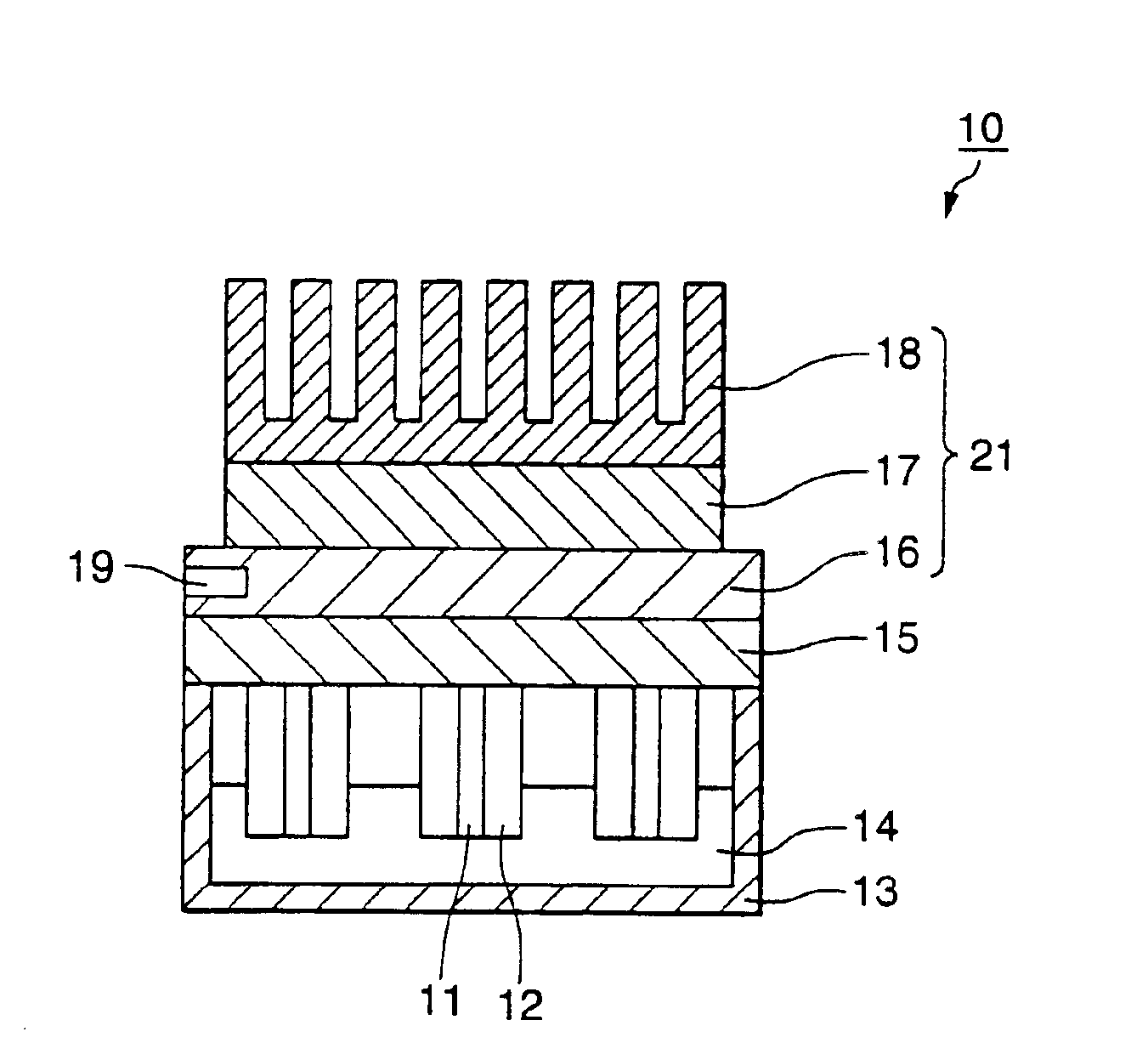
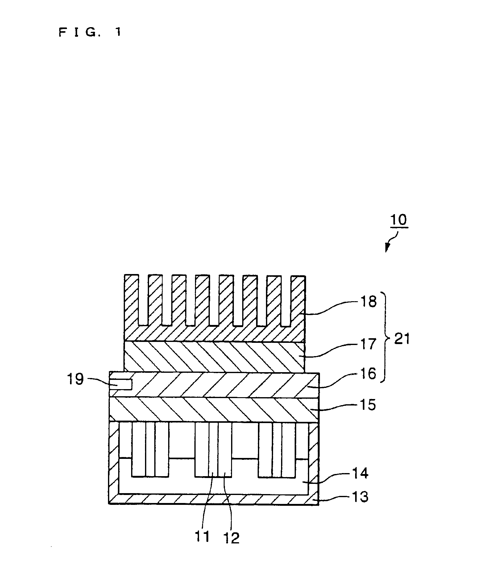
[0057]FIG. 1 is a partial cross section schematically illustrating a first embodiment of a gene detection system. In FIG. 1, the gene detection system 10 comprises an electrode substrate 15 for supporting an electrode, a plurality of pin-shaped electrodes 11 disposed on the electrode substrate 15, a heat insulating member 12 covering the peripheral surface of the electrodes, a rectangular container 13 open at the top, a solution 14 containing the target gene which is injected into the container, and heating and cooling means 21. The container 13 consists of a heat insulating material.
[0058]The heating and cooling means 21 comprises a soaking component 16 disposed in contact with the surface opposite the surface of the electrode support on which the electrodes are supported, a Peltier element 17 disposed in contact with the soaking component, and a heat sink 18 disposed in contact with the Peltier element to release the heat of the Peltier element. The soaking component 16 comprises a temperature sensor 19. The controller described below is connected to the Peltier element 17 and the temperature sensor 19.
[0059]The surface of the pin electrodes 11 is entirely gold-plated, and the electrode substrate 15 consists of a ceramic material. The heat insulating member 12 consists of PEEK.
[0060]Probes of the same gene sequence are immobilized on the individual electrodes 11. Probes that may be used include chemically synthesized DNA or genes which have been extracted from a biological material, then cleaved with restriction enzymes, and then purified such as by isolation through electrophoresis. The probe sequence should be determined beforehand. Probes may be sequenced by common means.
[0061]Well-known methods may be employed to immobilize the probes on the electrodes. For example, in the case of gold probes, thiol groups (SH groups) may be introduced into the probe itself to allow the probe to bind to the electrode through the gold-sulfur coordinate linkages between gold and sulfur. Methods for introducing thiol groups into probes themselves include the method of Mizuo Maeda, Koji Nakano, Shinji Uchida, and Makoto Takagi in Chemistry Letters, 1805-1808 (1994), and the method of B. A. Connolly in Nucleic Acids Rs., 13, 4484 (1985). Probes with thiol groups obtained by the above methods are added in the form of drops onto the gold electrodes and are allowed to stand for several hours at a lower temperature (such as 4° C.) to allow the probe to become immobilized on the gold electrodes.
[0062]In another method, glassy carbon can be oxidized with potassium permanganate to introduce a carboxylic acid into the electrode surface to form amide bonds with modified amino groups and immobilize the probe. A method for immobilizing probes on glassy carbon is described by Kelly M. Millan and Susan R. Mikkelsen in Analytical Chemistry, 65, 2317-2323 (1993). For pretreatment before gold plating the surfaces of electrodes or for SH-gold bonds, see, for example, C. D. Bain in J. Am. Chem. Soc., 111, pp. 321˜1989, or J. J. Gooding in Anal. Chem., 70, P2396˜1998.
Detection Method Using Gene Detection System in the First Embodiment
[0063]FIGS. 2 and 3 illustrate a detection method using the gene detection system in FIG. 1.
[0064]FIG. 2 is a block diagram illustrating the layout of the controller 20, Peltier element 17, and temperature sensor 19, and FIG. 3 is a flow chart showing the operation of of the controller 20 in FIG. 2.
[0065]As illustrated in FIG. 2, the controller 20 comprises an output side terminal 31, input side terminal 32, a temperature controller 33 made of a microcomputer system or the like connected to the output side terminal 31 and input side terminal 32, and a target temperature input means 34 connected to the temperature controller 33. The temperature sensor 19 is connected to the input side terminal 32. The Peltier element 17 is connected to the output side terminal 31. When the target temperature is input by the target temperature input means 23, the target temperature Tx is set by the temperature controller 33. The temperature controller 33 compares the target temperature (Tx) and the measured temperature (T) input by the input side terminal 32, and transmits a processing signal to the output side terminal 31 according to the results to either turn on or off the current of the Peltier element 17 or to switch the direction of the current.
[0066]A more detailed description is given below with reference to the flow chart of FIG. 3.
[0067]The target temperature (Tx) and the hybridization time (Δt) are first input by the target temperature input means 34 to set the target temperature Tx and time Δt in the memory of the temperature controller 33. When the detection process is started (S1), the temperature controller 33 reads the measured temperature (T) from the temperature sensor 32 and determines whether or not the measured temperature T matches the target temperature Tx (S2). When the measured temperature T does not match the target temperature Tx, the temperature controller 33 determines whether the measured temperature T is lower than the target temperature Tx (S4).
[0068]If the temperature T is lower than the target temperature Tx (T 17 (S5), and positive thermal flux is propagated from the Peltier element 17 through the soaking component 16 to the electrode substrate 15 and electrodes 11 to heat the solution near the electrode surface. When the measured temperature T matches the target temperature Tx (T=Tx), the Peltier element 17 is turned off (S3).
[0069]If the temperature T is higher than the target temperature Tx (T>Tx), power is applied to the wiring B of the Peltier element 17 (S6), and negative thermal flux is propagated from the Peltier element 17 through the soaking component 16 to the electrode substrate 15 and electrodes 11 to cool the solution near the electrode surface.
[0070]The feedback control of the Peltier element 17 by the temperature controller 33 based on the measured temperature of the temperature sensor 19 thus keeps the measured temperature T at the target temperature Tx.
[0071]At that time, due to the presence of the soaking component 16, the temperature of the electrode substrate 15 is kept at a constant level, ensuring that thermal flux having the same quantity of heat is propagated to the surface of each of the electrodes 11. Because the electrode substrate 15 and the electrodes 11 are made of material having high thermal conductivity, the temperature of the electrode surface and the temperature of the soaking component 16 measured by the temperature sensor 19 are substantially the same. Heating and cooling are thus managed while adjusted in such a way that the measured temperature of the temperature sensor 19 is continuously varied.
[0072]Only the portion of solution near the tips of the electrodes immersed in the solution are at the target temperature Tx while the measured temperature T matches the target temperature Tx. Conditions where T=Tx will result in the hybridization of the target gene having a sequence complementary to the probe, forming double strands. The temperature control process may involve actuating a timer when the measured temperature T matches the target temperature Tx, and employing an alarm to signal the conclusion of hybridization when Δt has elapsed. Following the conclusion of hybridization, various types of electrical signals can be detected to detect the sequence of the target gene.
[0073]Hybridization brought about in the manner described above permits rapid, highly sensitive detection with minimal solution volume heated or cooled to the target temperature Tx or maintained at the target temperature Tx.
[0074]Well-known methods can be employed to prepare the solution containing the target gene and to undertake hybridization.
[0075]The present embodiment was of an example in which the Peltier element is actuated and controlled by the controller, but the Peltier element and the heat sink may both be controller by the controller.
Another Detection Method Using the Gene Detection System in the First Embodiment
[0076]Another detection method using the gene detection system in the first embodiment in FIG. 1 is illustrated below with reference to FIG. 4. FIG. 4 is a schematic illustrating the relationship of the detection current to temperature in this example of detection.
[0077]As illustrated in FIG. 4, the detection current is continuously measured as the temperature of the probe-immobilizing support is increased. As illustrated in FIG. 4(a), when only fully matching DNA is hybridized to the probe, the detection current varies considerably at the measured temperature TA of the temperature sensor. When both fully matching DNA and mismatched DNA are hybridized as illustrated in FIG. 4(b), current caused by the mismatched DNA is produced at the measured temperature TB in addition to the current caused by the fully matched DNA. The changes in current at measured temperature TA and the changes in current at measured temperature TB can be measured to calculate for each electrode the proportion of fully matched DNA and mismatched DNA (ratio of amounts in which they are present) in the DNA hybridized to the probe.

Example

Second Embodiment of the Gene Detection System, and Detection Using Such System
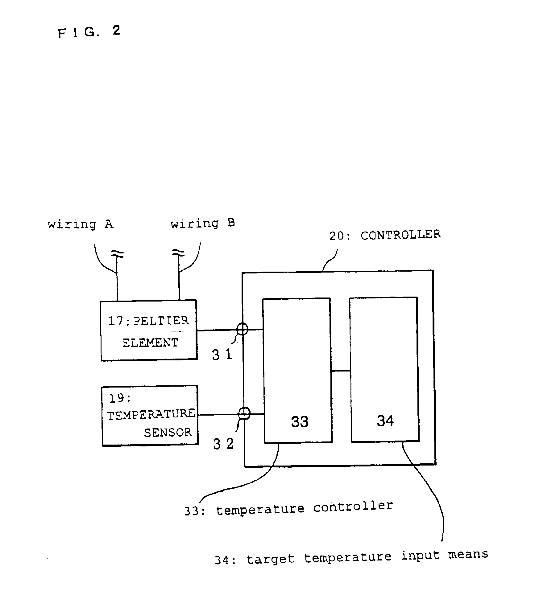
[0078]This embodiment differs from the gene detection system in the first embodiment in that probes with differing gene sequences are immobilized on respective electrodes. The layout of the Peltier element, temperature sensor, and controller in this embodiment is the same as in FIG. 2.
[0079]The detection process using the gene detection system in this embodiment is illustrated below with reference to FIGS. 5 and 6. FIG. 5 is a flow chart of the controller operation. FIG. 6 illustrates the relationship between temperature and time in the detection in this embodiment.
[0080]The target gene is first hybridized to the probe at a temperature lower than the target temperatures (Ti) to form double strands. The solution containing the double strands is injected into the container 13.
[0081]Next, as illustrated in FIG. 5, the target temperature Ti is input by the target temperature input means 34 to set the target temperature Ti in memory (not shown) of the temperature controller 33 (S7). Because different probes are immobilized on the electrodes in this embodiment, the optimal target temperature is input for each probe. The input data are sorted in order from the lowest target temperature (i=1, i=2, . . . i=max) and tabulated.
[0082]A command to begin the detection process from the input means (not shown) of the controller 20 starts the heating and the measurement by the temperature sensor to begin the detection process for i=1 (S8). The heating process takes place continuously through the operation of the Peltier element 17, for example, until the process is concluded.
[0083]When the detection process starts for i=1, the temperature controller 33 reads the target temperature T1 from memory (S9). The electrode reaction response is measured (S11) on the basis of the time it takes for the measured temperature T determined by the temperature sensor to reach the target temperature T1 (S10). As the measured temperature increases, the hybridized double strands with lower homology dissociate, and only double strand configurations for which T1 is the optimal temperature remain by the time the target temperature T1 has been reached, allowing the electrode reaction response to be measured on the basis of that time.
[0084]It is then determined whether 1=max has been reached (S12). If max has not been reached, the temperature controller 33 reads T2 from memory (S13). The detection process proceeds in this manner to the next i+1 (S13) whenever i is not max (S12). When i is max (S12), the detection process is complete (S14).
[0085]According to the illustration in FIG. 5, as the temperature of the probe-immobilizing support is increased at a constant rate, an electrode reaction response is measured on the basis of the time (t1) it takes for the measured temperature T of the temperature sensor to reach the target temperature T1, the next electrode reaction response is measured on the basis of the time (t2) it takes to reach the next target temperature T2, and another electrode reaction response is measured on the basis of the time (t3) it takes to reach the target temperature T3. Double strands can thus be detected on the basis of the relationship between the measured temperature and the electrode reaction response.
[0086]Genes can be automatically detected rapidly and with high sensitivity by measuring the electrode reaction response based on the time it takes the temperature to reach the various optimal temperatures as the temperature of each electrode is thus uniformly varied. This has the merit of permitting uniform detection on the basis of the time it takes to reach the various optimal temperatures (Tx) when a plurality of types of probes are immobilized, as in the present embodiment.
[0087]The example in the above embodiment was of different probes immobilized on a plurality of electrodes, but the present invention is equally applicable to cases in which at least two or more types of probes are immobilized, cases with one electrode, and cases in which one type of probe is immobilized on all electrodes.

Example

Third Embodiment of the Gene Detection System
[0088]In contrast to the gene detection system of the first embodiment, advantages of this embodiment are that the same number of electrode substrates, soaking components, temperature sensors, heat sinks, and Peltier elements are provided for each electrode, where the respective Peltier element is actuated as the temperature of each of the plurality of soaking components is measured, so as to independently control the temperature of each of the electrode substrates, and that probes with differing gene sequences are immobilized on the electrodes.
[0089]In this embodiment, the controller comprises a plurality of Peltier elements, and a plurality of output and input terminals connected to their respective temperature sensors. The unique Tx for each of the plurality of probes is set by the target temperature input means of the controller.
[0090]In this embodiment, the electrodes must be disposed far enough apart from each other to avoid overlapping thermal flux convection ranges (temperature boundary layers) near the surface of the electrodes in the solution.
[0091]An advantage of this embodiment is that the temperature of each electrode substrate can be independently controlled by the controller, enabling simultaneous detecting of the hybrid state of probes having different target temperatures Tx per detection cycle, and thus rapid and highly sensitive detection.
[0092]This embodiment is applicable not only to cases in which different probes are immobilized on the plurality of electrodes, but also cases in which at least two or more types of probes are immobilized. For example, in cases where two or more probes are immobilized, each probe can be provided with a shared electrode substrate, soaking component, temperature sensor, heat sink, and Peltier element.
Gene Detection Device Comprising the Gene Detection System of the First Embodiment
[0093]FIG. 7 is an oblique view of the entire structure of the gene detection device in the present invention.
[0094]In FIG. 7, the gene detection device 100 relating to the present invention comprises a detection chip 104, a measuring device with a mounting port 103 for inserting the detection chip 104, and a personal computer 101.
[0095]FIG. 8 illustrates the structure of the detection chip 112. As shown in FIG. 8, the chip 112 comprises a container 114 with a sink 118 formed in the center, and a main unit 115 to which the container 114 is detachably mounted. The main unit 115 comprises an electrode substrate 121, a plurality of pin-shaped electrodes 110 which are supported on the electrode substrate 121 and which uniformly project into the area corresponding to the sink 118 of the container 114, a soaking component 122 disposed in contact with the surface opposite the surface on which the electrodes 110 of the electrode substrate 121 are supported, and a temperature sensor (not shown) for measuring the temperature of the soaking component 122.
[0096]The top of the mounting port 103 of the personal computer 101 is provided with a Peltier element 123, and a heat sink disposed in contact thereabove. The controller (not shown) is provided inside the personal computer 101.
[0097]After solution containing the target gene(s) is injected into the sink 118, the main unit 115 is mounted on the container 114, and the detection chip 112 is inserted into the mounting port 103, thus bringing the soaking component 122 of the detection chip 112 into contact with the Peltier element 123 on the measuring device 102 side. The layout in the gene detection device 100 is thus as illustrated in FIG. 1. The target temperatures TX are input from the keyboard of the personal computer 101, which is the target temperature input means of the controller. Hybridization is then brought about by changing the temperature to Tx in the same manner as the detection method using the gene detection system in FIG. 1 and the controller in FIG. 2. An intercalator is then introduced into the double strands formed by the hybridization, the electrode terminal 27 and electrode terminal 20 of the main unit 115 are connected to the reception terminals (not shown in figure) of the measuring device 102 and are connected to a voltage circuit through a selection switch, and weak voltage is applied across the shared electrode and each electrode 110 to allow weak current to flow through the voltage circuit and the shared electrode between the electrodes 110 and the position labeled by the intercalator. Genes are detected by detecting the current.
[0098]The gene detection device in this embodiment can be used for highly sensitive, rapid detection because of the extremely low volume of the solution subject to temperature control.
[0099]The soaking component of the detection chip in this embodiment was described as comprising a temperature sensor, but the personal computer may also comprise a temperature sensor connected to the soaking component in order to measure the temperature.
[0100]The gene detection device comprising the gene detection system in the second embodiment may also be constructed in the same manner as this embodiment.
[0101]The example in the above embodiment was of adjustments which were made as the temperature was continuously increased, but the temperature may also be continuously decreased, as well as increased or decreased stepwise.
[0102]The example in the above embodiment was also of a plurality of pin-shaped electrodes disposed in the form of arrays on the electrode substrates, but the invention is not limited to this option.
[0103]In the example in the above embodiment, probes were immobilized on the electrodes, and electrical signals were detected, but other options include immobilizing probes on a probe-immobilizing support that is not an electrode, detecting fluorescent signals, and the like.
INDUSTRIAL APPLICABILITY
[0104]In the gene detection system, gene detection device employing such a system, detection method, and gene detection chip of the present invention, the temperature of only the solution near the surface of the electrode or the probe-immobilizing support is controlled, resulting in the possibility of rapid (high throughput ), highly sensitive gene detection.
[0105]In particular, the present invention ensures that the optimal temperature Tx can be set, so as to enable reliable detection of SNPs.
[0106]The gene detection system, gene detection device employing such a system, detection method, and gene detection chip of the present invention are effective means for the analysis of gene expression or the analysis of genetic mutations in the biochemical and medical fields, and can be useful in gene diagnostics, preventive medicine, gene therapy, and drug design.

PUM

PropertyMeasurementUnit
Temperature
Sensitivity
Thermal properties

Description & Claims & Application Information

We can also present the details of the Description, Claims and Application information to help users get a comprehensive understanding of the technical details of the patent, such as background art, summary of invention, brief description of drawings, description of embodiments, and other original content. On the other hand, users can also determine the specific scope of protection of the technology through the list of claims; as well as understand the changes in the life cycle of the technology with the presentation of the patent timeline. Login to view more.

Similar technology patents

Personal aquatic safety device

PendingUS20210403132A1rapid detectionrapid signal
Owner:POURMASIHA NILOUFAR

Compositions for the treatment of cancer, and methods for testing and using the same

InactiveUS20140073586A1rapidly and effectively determinerapid detection
Owner:RUTGERS UNIVERSITY

Network traffic analyzing device, network traffic analyzing method and network traffic analyzing system

ActiveCN101540695Areliable analysishigh precision analysis
Owner:OKI ELECTRIC IND CO LTD

Kit and method for detecting single nucleotide polymorphism

InactiveUS20180245140A1rapid and accurate mannerrapid detection
Owner:HEIMBIOTEK INC

Reduced-level shift overflow detection

ActiveUS8601040B2rapid detection
Owner:TEXAS INSTR INC

Foaming amount estimation system of foaming machine

PendingCN114161648Areliable analysiseasy to operate
Owner:李林霞

Classification and recommendation of technical efficacy words

  • reliable analysis
  • rapid detection

Network traffic analyzing device, network traffic analyzing method and network traffic analyzing system

ActiveCN101540695Areliable analysishigh precision analysis
Owner:OKI ELECTRIC IND CO LTD

Foaming amount estimation system of foaming machine

PendingCN114161648Areliable analysiseasy to operate
Owner:李林霞

License plate detection method based on deep learning

InactiveCN106022232ARapid detectionsmall amount of calculation
Owner:CHENGDU XINEDGE TECH

Method for rapidly detecting mixing uniformity of powdery material

InactiveCN102661911ARapid detectionStrong sampling randomness
Owner:XIAN UNIV OF TECH

Symmetrically Branched Polymer Conjugates and Microarray Assays

InactiveUS20080114077A1rapid detection
Owner:ANP TECH INC

Sensor for detecting explosive, and preparation method thereof

InactiveUS20150147818A1rapid detectionhigh sensitivity
Owner:POSTECH ACAD IND FOUND

Supercooling method and supercooling apparatus

ActiveUS20100199692A1optimal temperaturerapid detection
Owner:LG ELECTRONICS INC
Why Eureka
Try Eureka