Fast bandgap reference circuit for use in a low power supply A/D booster

a reference circuit and booster technology, applied in the field of electrical circuits, can solve the problems of increasing the difficulty of obtaining the device speed requirements, the gain-bandwidth product of the reference circuit may be inadequate, and the assumption of validity, etc., and achieve the effect of fast and stable, low fvr

Inactive Publication Date: 2005-05-17
INFINEON TECH LLC
View PDF7 Cites 55 Cited by
  • Summary
  • Abstract
  • Description
  • Claims
  • Application Information

AI Technical Summary

Benefits of technology

[0011]In yet another aspect of the invention, the first resistance of the current generation circuit comprises a poly resistor without silicide that has a negative temperature coefficient. This provides a reference current having a positive function of temperature to lower the effective ∂Vbe/∂T, which advantageously lowers the FVREF to keep the voltage generation circuit operating in saturation particularly at low supply voltages, thereby providing voltage reference stability.
[0012]In still another aspect of the present invention, a smart clamping circuit comprises one or more diode-connected tr

Problems solved by technology

However, in many cases, this is not a valid assumption.
Under some of these conditions, the gain-bandwidth product of the reference circuit may be inadequate.
Further, as supply voltage levels decrease due to these higher density architectures, device speed requirements may be increasingly difficult to obtain, particularly at low supply voltage a

Method used


Image

  • Fast bandgap reference circuit for use in a low power supply A/D booster
  • Fast bandgap reference circuit for use in a low power supply A/D booster
  • Fast bandgap reference circuit for use in a low power supply A/D booster

Examples


Embodiment Construction

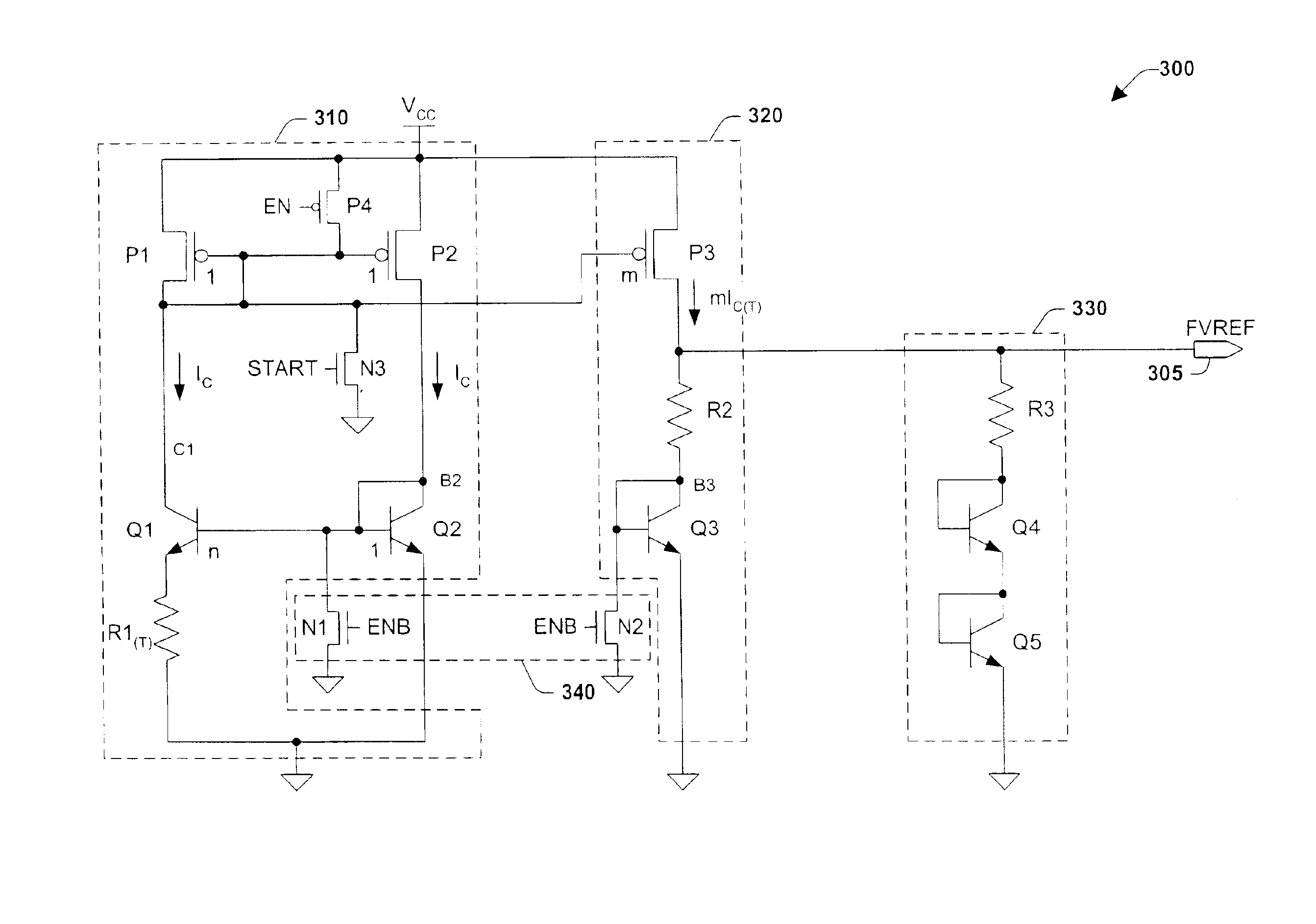
[0020]The present invention will now be described with reference to the drawings, wherein like reference numerals are used to refer to like elements throughout. The present invention relates to an electronic circuit for producing a fast voltage or current reference which is substantially independent of VCC fluctuations, and which may be used, for example, to provide a fast low level reference voltage for a voltage booster for the read mode operations of memory cells. The invention comprises current and voltage generation circuits, a smart clamping circuit, and a discharge circuit.

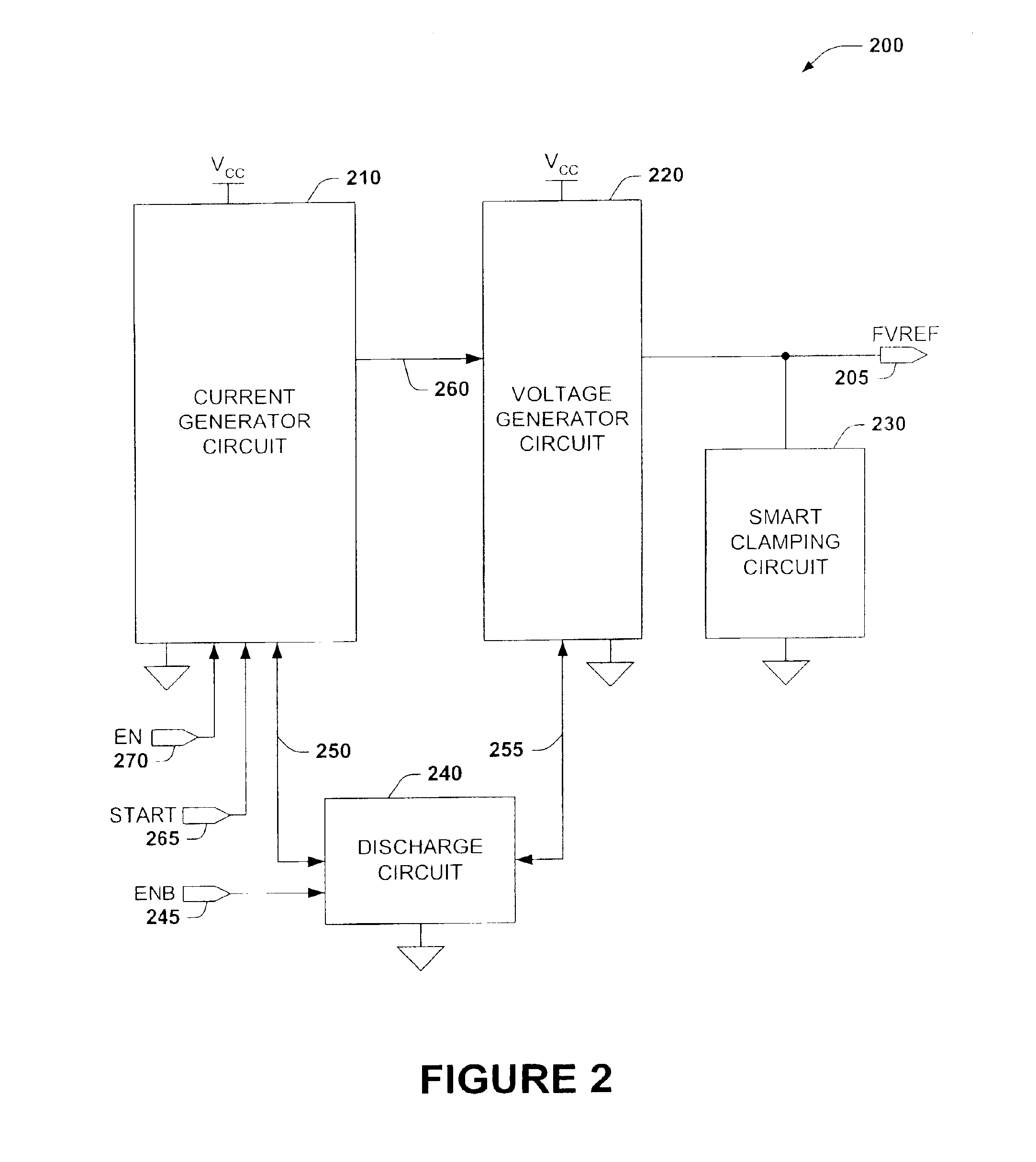
[0021]FIG. 2 illustrates a system level functional block diagram of an exemplary fast bandgap voltage reference circuit 200, for producing a fast voltage reference FVREF 205, which may be used, for example, to provide a fast settling low level reference voltage for a voltage booster for the read mode operations of memory cells. Fast bandgap circuit 200 comprises a current generation circuit 210, a voltage g...


PUM


Abstract

A bandgap reference circuit includes a current generation circuit connected to a voltage generation circuit connected to a smart clamping circuit, and a discharge circuit connected to the current generation circuit and the voltage generation circuit. The discharge circuit initially discharges a potential in the current and voltage generation circuits to improve repeatability. A start circuit within the current generation circuit then initializes the reference output at about the supply voltage to improve the speed and settling time of the output signal. The current generation circuit sources a current to the voltage generation circuit that translates the current having a positive function of temperature +TC into a reference voltage. The smart clamping circuit further generates a clamping voltage having a negative function of temperature −TC and a load resistance. The clamping voltage and the load resistance are applied across the reference voltage quickly reducing the reference voltage particularly at high temperatures and during start-up to a final level, thereby producing a fast and stable reference voltage.

Description

FIELD OF INVENTION[0001]This invention relates to electronic circuits and more particularly relates to voltage and current reference circuits.BACKGROUND OF THE INVENTION[0002]Voltage and current reference circuits find many applications in electronic circuits including Flash and other types of electronic memory device applications. The bandgap reference circuit is a common circuit solution for supplying a voltage or current reference for such applications. FIG. 1 is a prior art bandgap circuit 100 and operates generally as follows. P1 and P2 act as a standard MOS current mirror providing current to Q1 and Q2 which are configured as a bipolar current mirror. Q1 and Q2 are sized differently; therefore, although they conduct the same current, they have different current densities. Therefore, there will be a difference in their Vbe voltages and the difference will be reflected in the current through R1. VREF is a voltage reference that is a function of the current through R2 and the bas...

Claims


Application Information

Patent Timeline
IPC IPC(8): G05F3/08G05F3/16G05F3/30
CPCG05F3/30
Inventor LE, BINH QUANGLY, CATHY THUVANCLEVELAND, LEECHEN, PAU-LING
Owner INFINEON TECH LLC
Why Eureka
Try Eureka