Method and apparatus for optimizing optical system and recording medium with program for optimizing optical system

a technology of optical system and recording medium, applied in the direction of adaptive control, reradiation, instruments, etc., can solve the problems of difficult to effectively optimize lenses, other optical performance such as an evaluation of mtf, not always optimized,

Inactive Publication Date: 2005-05-17
FUJI PHOTO OPTICAL CO LTD
View PDF5 Cites 63 Cited by
  • Summary
  • Abstract
  • Description
  • Claims
  • Application Information

AI Technical Summary

Problems solved by technology

Meanwhile, in the automated lens design using the merit function in view of only general aberration, although the optimal solution is effective for the evaluation of aberration, other optical performance such as an evaluation of the MTF is not always optimized.
However, there exist the following problems in that case.
The MTF has higher non-linearity with parameters than that of aberration, thus it is difficult to optimize lenses effectively as compared to the case where aberration is subjected to be evaluated.
Thus, the conventional algorithms for lens optimization are inappropriate for optimization on the evaluation subject having high non-linearity such as the MTF.
As described above, with conventional optimization techniques, it is difficult to efficiently realize lens optimization on the MTF.
There is another problem such that calculation for the MTF takes longer ti me than that for aberration.
Further, a process for obtaining the MTF from the result of ray tracing is complicated compared to that for obtaining aberration, resulting in requiring further longer time.
As described above, it is apparent that lens optimization on the MTF takes long time.
As described above, lens optimization method using the merit function on the MTF has various problems.
In such a lens design, however, manual work by a designer is required, so that high-speed calculation by a computer, which is an advantage of the automated design, cannot be fully utilized.

Method used


Image

  • Method and apparatus for optimizing optical system and recording medium with program for optimizing optical system
  • Method and apparatus for optimizing optical system and recording medium with program for optimizing optical system
  • Method and apparatus for optimizing optical system and recording medium with program for optimizing optical system

Examples


first embodiment

[First Embodiment]

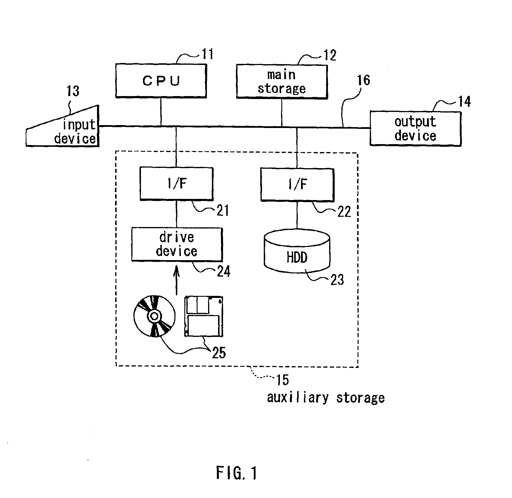
[0065]FIG. 1 shows the configuration of hardware of an apparatus for optimizing an optical system according to a first embodiment of the present invention. The apparatus for optimizing an optical system of the embodiment is a computer. More specifically, as shown in FIG. 1, the apparatus for optimizing an optical system comprises a central processing unit (CPU) 11, a main storage (internal storage) 12, an input device 13, output device 14 and an auxiliary storage (external storage) 15. Further, the apparatus for optimizing an optical system has a bus 16 which connects one component to another.

[0066]The CPU 11 controls each component and performs predetermined calculation on the basis of a program given. The main storage 12 is constituted of a random access memory (RAM), for example. The main storage 12 is mainly used for an area for the CPU 11 to operate. For example, the main storage 12 stores a program and data loaded from the auxiliary storage 15 and data calcul...

experimental example 1

[Experimental Example 1]

[0097]An experimental example of lens optimization using actual numeric values in which the method of optimizing an optical system and the apparatus therefor according to the first embodiment will be described below.

[0098]In this experimental example 1, a tessar type photographic lens as in FIGS. 4 and 5 is subject to optimization. FIG. 4 shows the configuration of a photographic lens 1 of the starting point before optimization. FIG. 5 shows lens data of the components of the photographic lens 1 as in FIG. 4 in numeric values. In FIG. 4, the line indicated by Zo represents an optical axis and the line indicated by Z1 represents a principal ray at the maximum field angle. The line indicated by 2 is the position of the plane of image formation. In FIG. 5, a surface number Si is the number of the ith lens surface incrementing from 1 of the closest lens to the object toward the image plane. In FIGS. 4 and 5, Rl represents the radius of curvature of the ith lens s...

second embodiment

[Second Embodiment]

[0111]A second embodiment of the present invention will be described herein below. The same elements as those in the first embodiment are indicated by the same reference numerals and the description is appropriately omitted in the following description.

[0112]With the second embodiment, MTF optimization in the first embodiment is applied to a so-called global optimization. The function to optimize the optical system according to the second embodiment is realized by executing an optimization program of the optical system of the second embodiment in an apparatus with the hardware configuration shown in FIG. 1 similar to the first embodiment.

[0113]With the first embodiment above, MTF optimization such that weights and target values for aberration are automatically adjusted is very efficient and speedy as compared to the conventional optimization. The MTF optimization is especially efficient when it is used with the global optimization. Optimization used in general is ...


PUM


Abstract

Optical properties with high non-linearity such as a modulation transfer function (MTF) are efficiently optimized at high speed compared to conventional methods. An optimal solution of an optical system is obtained in a first optimization unit using a merit function on aberration. Weights or target values of the merit function on aberration is automatically adjusted in a second optimization unit in a manner that an evaluated value of the MTF or the like approaches a desired value. The first optimization unit re-optimizes the optical system using the weights or target values which have been automatically adjusted. Thus, automated is a function equivalent to the operation which has been conducted by a designer such as adjustment to weights or target values.

Description

BACKGROUND OF THE INVENTION[0001]1. Field of the Invention[0002]The present invention relates to a method of optimizing an optical system which realizes automated design of an optical system, an apparatus for optimizing an optical system and a recording medium on which a program for optimizing an optical system is recorded.[0003]2. Description of the Related Art[0004]In recent years, it has been common to employ automated design using a computer for design of optical systems (simply referred to as “optical design” hereinafter). The automated optical design is realized by executing a design program on a computer. Thus, in performing the automated optical design, use of excellent design programs is an important factor to realize favorable optical design.[0005]Optical design is an operation to optimize design parameters of an optical system so that the optical system offers desired optical performance. The basic concept of the optimization of an optical system will be described herein ...

Claims


Application Information

Patent Timeline
Patent Type & Authority Patents(United States)
IPC IPC(8): G02B27/00G02B13/00G06F17/50
CPCG02B27/0012
Inventor YABE, AKIRA
Owner FUJI PHOTO OPTICAL CO LTD
Why Eureka
Try Eureka