Computerized methods for data loggers

a data logger and computerized technology, applied in the field of methods for operating data loggers, can solve problems such as permanent loss of important data, forgetting to reinitialize variables, and unplanned problems arising relative to this new capability

Inactive Publication Date: 2005-05-17
REMOTE DATA SYST
View PDF24 Cites 47 Cited by
  • Summary
  • Abstract
  • Description
  • Claims
  • Application Information

AI Technical Summary

Benefits of technology

[0016]The problem of a data logger user forgetting to initialize variables such as data memory pointers following a firmware upload is eliminated by providing a computerized method that recognizes the presence of new firmware, and in response, initializes variables automatically. The computerized method will work for any digital processor system having in-circuit programming capability. The method includes a step of determining the presence of new firmware in the processor system and a step of initializing the memory locations with predetermined values upon detecting the presence of new firmware. The determination can be made during or following an initial boot-up of the processor system.
[0017]As those skilled in the art will be familiar with, there are various ways to test for the status of an unknown variable. One way to determine the presence of a new firmware upload is to check the status of a new firmware flag. The new firmware flag can be embedded into the firmware as it is programmed into a firmware memory block belonging to a digital processor system. The processor checks the new firmware flag's status after initial boot-up. If the status of the new firmware flag signifies the presence of new firmware, then appropriate variables are initialized to predetermined values. Upon completion of the variable initializations, the status of the new program flag is altered such that it no longer represents the presence of new firmware. In this way, subsequent boot-ups will not result in the re-initialization of previously set variables.

Problems solved by technology

While the ability to revise a data logger's firmware is a significant advance, an unforeseen problem has surfaced relative to this new capability.
The problem occurs whenever a user programs new firmware into the data logger, but forgets to reinitialize variables such as data memory pointers, etc.
Forgetting to initialize data memory pointers after a firmware upload can result in a permanent loss of important data.
Another previously unsolved problem pertains to attaining baud rates greater than 19.2 kbps between a sleep mode operated data logger and an external user interface device such as a PDA.
Up to now, a data logger operating from a sleep mode could not receive a data stream at a baud rate higher than 19.2 kbps because of delays resulting from the data logger's wake-up procedures.
Unfortunately, operating outside of a sleep mode during a communication session results in excessive energy consumption of a data logger's primary power source.
Still yet another problem, involves estimating remaining battery capacity of the primary power source.
While some of these prior art methods provide reasonably accurate results, they do so at significant disadvantages relative to low power data logger operation.
Secondly, these extra sensors require power to operate, creating additional loads for the data logger's battery.
Another problem lacking an adequate solution up to this point, is due to primary power source disruptions that result in the loss of crucial variable data such as data memory pointers, alarm intervals and the like.
The most worrisome power disruptions happen during transportation of data loggers to field sites.
Power disruptions can occur when the battery powering a data logger is shaken in its holder, causing momentary loss of power as the battery disconnects and reconnects to the holder's terminals.
Another lengthier, yet predictable power disruption occurs whenever the battery is removed from its holder making room for its replacement.
If the battery is not quickly reinstalled, residual energy stored in filter capacitors will drain down to a point to which volatile memory locations are corrupted.

Method used


Image

  • Computerized methods for data loggers
  • Computerized methods for data loggers
  • Computerized methods for data loggers

Examples


Embodiment Construction

[0031]In the following description it is to be understood that descriptive terms and the like are words of convenience and are not to be construed as limiting terms. It is also to be understood that the illustrations are for the purpose of describing preferred embodiments of the invention and are not intended to limit the invention thereto.

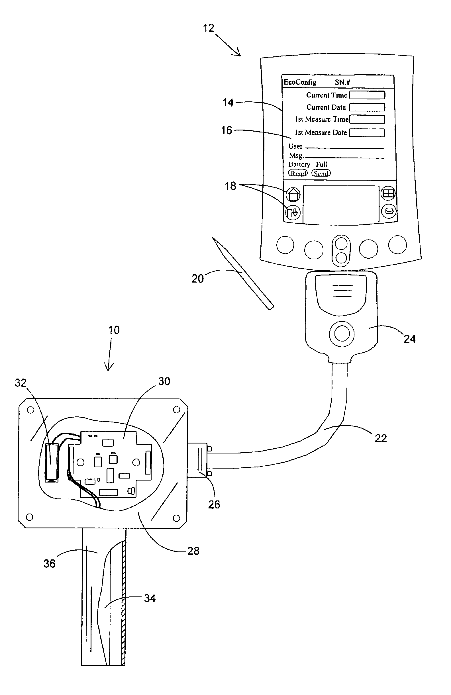
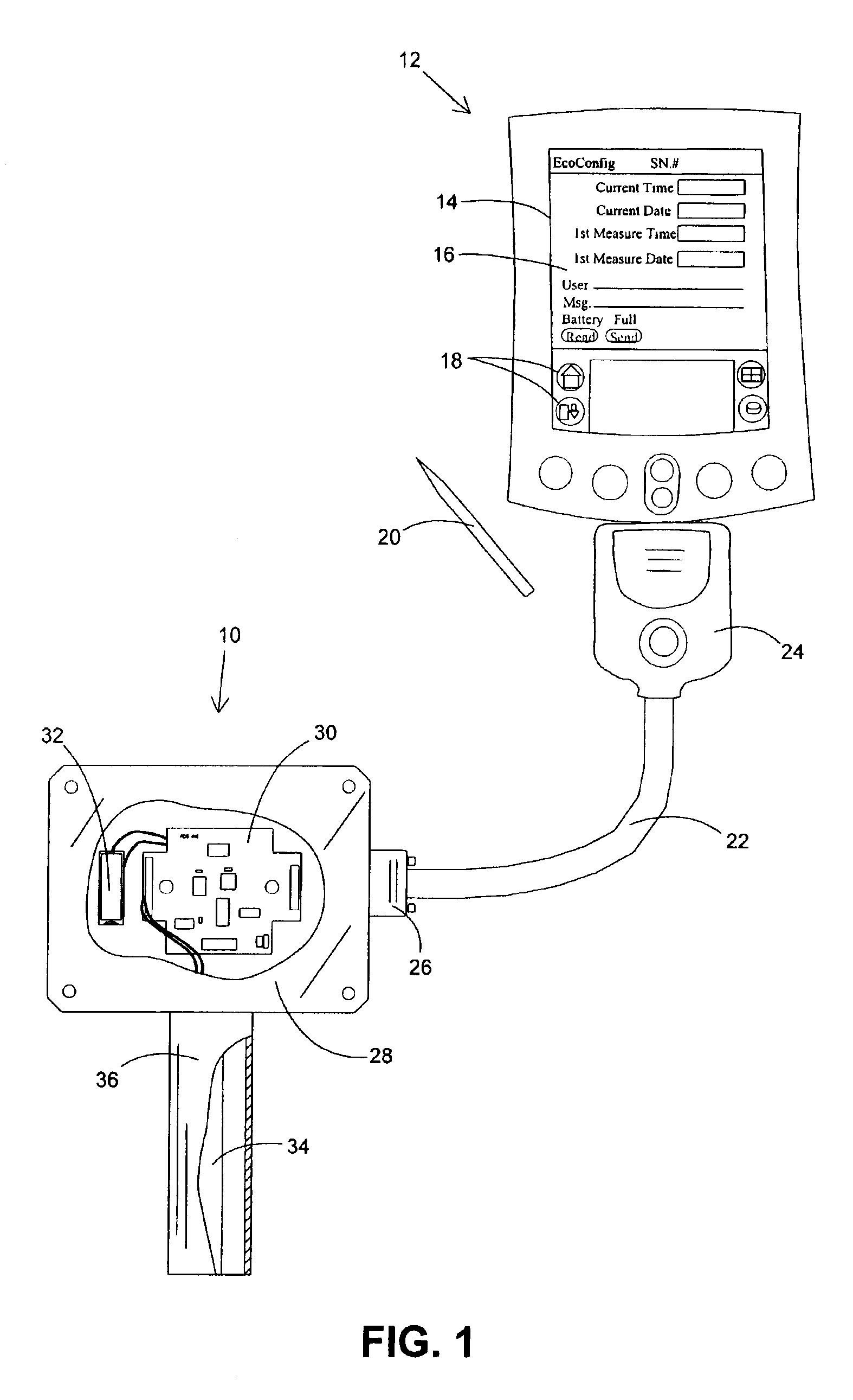
[0032]FIG. 1 shows a data logger 10 in communication with an external user interface device 12, which is shown in FIG. 1 as a personal digital assistant (PDA). User interface device 12 includes a display 14 used to present a user with a graphical user interface 16. Icons 18 represent various user selectable software applications or functions. Icons 18 can be selected using a selection device 20.

[0033]A communications cable 22 provides a communications channel between data logger 10 and user interface device 12. Connector 24 attached to one end of cable 22 is for temporarily connecting cable 22 to a communication port belonging to user interface de...


PUM


Abstract

The present invention provides methods for operating data loggers and in particular, software techniques useful for controlling the critical functions of a low-power-battery-operated data logger. One method initializes various memory locations upon a detection of new firmware. Another method allows a processor system belonging to a data logger to receive a high baud rate data stream while being operated in a sleep mode. Yet another method provides a highly efficient process for estimating the remaining battery capacity of a data logger's primary power source. Finally, a method is provided for protecting volatile variables during a disruption of primary power. The protected variables are written to non-volatile memory using parasitic power only.

Description

BACKGROUND OF THE INVENTION[0001](1) Field of the Invention[0002]The present invention relates to methods for operating data loggers. In particular, the invention provides software techniques useful for controlling the critical functions of low-power-battery-operated data loggers.[0003](2) Description of the Prior Art[0004]Generally speaking, data loggers are devices that record measurements obtained from electronic sensors that sense physical properties such as temperature, pressure, electrical current and voltage among others. A conventional data logger is made up of a digital processor operationally connected to a non-volatile memory bank for storing measurements obtained from electronic sensors in communication with the data logger. Other major components include at least one digital communication port for communicating with an external user interface device such as a personal computer (PC) or personal digital assistant (PDA) and a real-time clock for keeping track of time as we...

Claims


Application Information

Patent Timeline
Patent Type & Authority Patents(United States)
IPC IPC(8): G06F12/14G06F15/00G06F19/00G06F1/32G06F9/445
CPCG06F1/3203G06F8/665Y02B60/183G06F8/654Y02D10/00
Inventor DORNY, JONATHANGEORGE, ROBERT
Owner REMOTE DATA SYST
Why Eureka
Try Eureka