Magnetorheological fluid vibration isolator

a fluid vibration isolation and magnetorheological technology, applied in mechanical devices, machine supports, shock absorbers, etc., can solve the problems of fluid leakage, rapid wear of sealing devices incorporating dynamic type sealing, and maintenance of good lateral alignment of moving components, so as to increase the stiffness of the second load path, increase the effective viscosity of the fluid, and the effect of significant variation of the effective stiffness of the devi

Inactive Publication Date: 2005-05-24
MOOG INC
View PDF17 Cites 22 Cited by
  • Summary
  • Abstract
  • Description
  • Claims
  • Application Information

AI Technical Summary

Benefits of technology

[0014]The magnetorheological damping portion of the device also serves as a means to significantly vary the effective stiffness of the device. The application of a strong magnetic field to the damping portion and resulting stark increase in effective viscosity of the MR fluid effectively locks the top cap to the bottom cap via the piston and fluid chamber structure and thus causes the stiffness of the second load path to increase dramatically such that it is much higher than that in the first load path. The overall device stiffness can thus be varied from a relatively low stiffness level where the flexure structure stiffness governs to a much higher overall device stiffness where the serial stiffness of the top cap, piston, and bottom cap govern.
[0015]The clearance space in the inner radius wall of the fluid chamber is enclosed by use of two bellows. A first bellows attaches and seals between the bottom portion of the fluid chamber and the bottom surface of the connecting plate. A second bellows attaches and seals between the top portion of the fluid chamber and the top surface of the connecting plate. The two bellows thus attached between the connecting plate and their respective portions of the fluid chamber allow for longitudinal movement of the piston and its toroidal displacement body within the fluid chamber and provide for sealing of the toroidal displacement body within the fluid chamber without the use of dynamic seals.
[0016]The top and bottom caps being laterally aligned by the short, laterally stiff, cylindrical flexure body, provide for the lateral alignment of the piston and toroidal displacement body relative to the fluid chamber. The toroidal displacement body, being part of the piston connected to the top cap, thus moves up and down in the fluid chamber with the movement of the top cap relative to the bottom cap as allowed for through the longitudinal compliance of the cylindrical flexure structure.
[0017]In the preferred embodiment electromagnetic coils are positioned in the radially inner and outer walls of the fluid chamber such to induce a magnetic field in the volume of the magnetorheological fluid surrounding the toroidal displacement body. In the longitudinal motion of the top cap relative to the bottom cap, the toroidal displacement body displaces magnetorheological fluid from the top of the toroidal displacement body to the bottom of the body, and vice-versa, through a gap between the walls of the fluid chamber and the surfaces of the toroidal displacement body. The effective or that is apparent viscosity of the magnetorheological fluid is varied by varying the electrical current supplied to the coils and thus varies the effective damping of the device. The damping and stiffness of the device and the support of the payload overall can thus be tuned to minimize or change the fundamental resonance modes associated with a payload mounted to a vibration isolation support.

Problems solved by technology

Problems present in MR fluid damping devices of the prior art include fluid leakage and rapid seal wear in devices incorporating dynamic type sealing, i.e. where surfaces slide over one another such as a piston rod sliding through a concentric lip seal.
The maintenance of good lateral alignment of the moving components of the damper relative to the fixed components and the support of off-axis moment loading is also problematic within devices of the prior art.
Tighter seals and bushings are often used for improved alignment and moment support but cause greater friction loads and stiction effects between the moving components.
Devices of the prior art have thereby been relatively intolerant to off-axis moment loading.
Additionally, this device does not provide for static load carrying except at the end of travel points of the piston.
Often damping mechanisms of the prior art offer damping capability only and do not provide static load carrying capability.
The drawbacks with the use of elastomeric elements, however, are the non-linear load / deflection characteristics imparted to the device and the relatively low strength capabilities of the elastomeric elements which limit the static load carrying capability of the device.

Method used


Image

  • Magnetorheological fluid vibration isolator
  • Magnetorheological fluid vibration isolator
  • Magnetorheological fluid vibration isolator

Examples


Embodiment Construction

[0032]Described in detail below is a magnetorheological fluid device offering vibration isolation and magnetorheological fluid modulated damping in a high load carrying and compact form. In the description, for purposes of explanation, many specific details are set forth in order to provide a thorough understanding of the present invention. However, the present invention may be practiced without these specific details, as would be obvious to one skilled in the art.

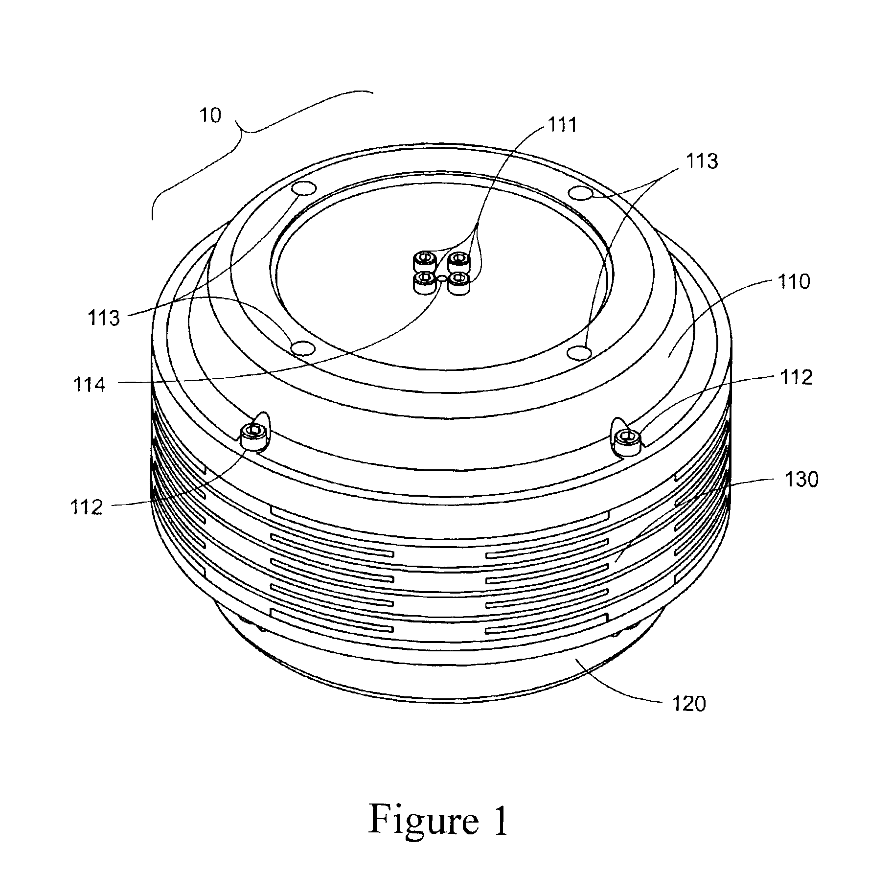
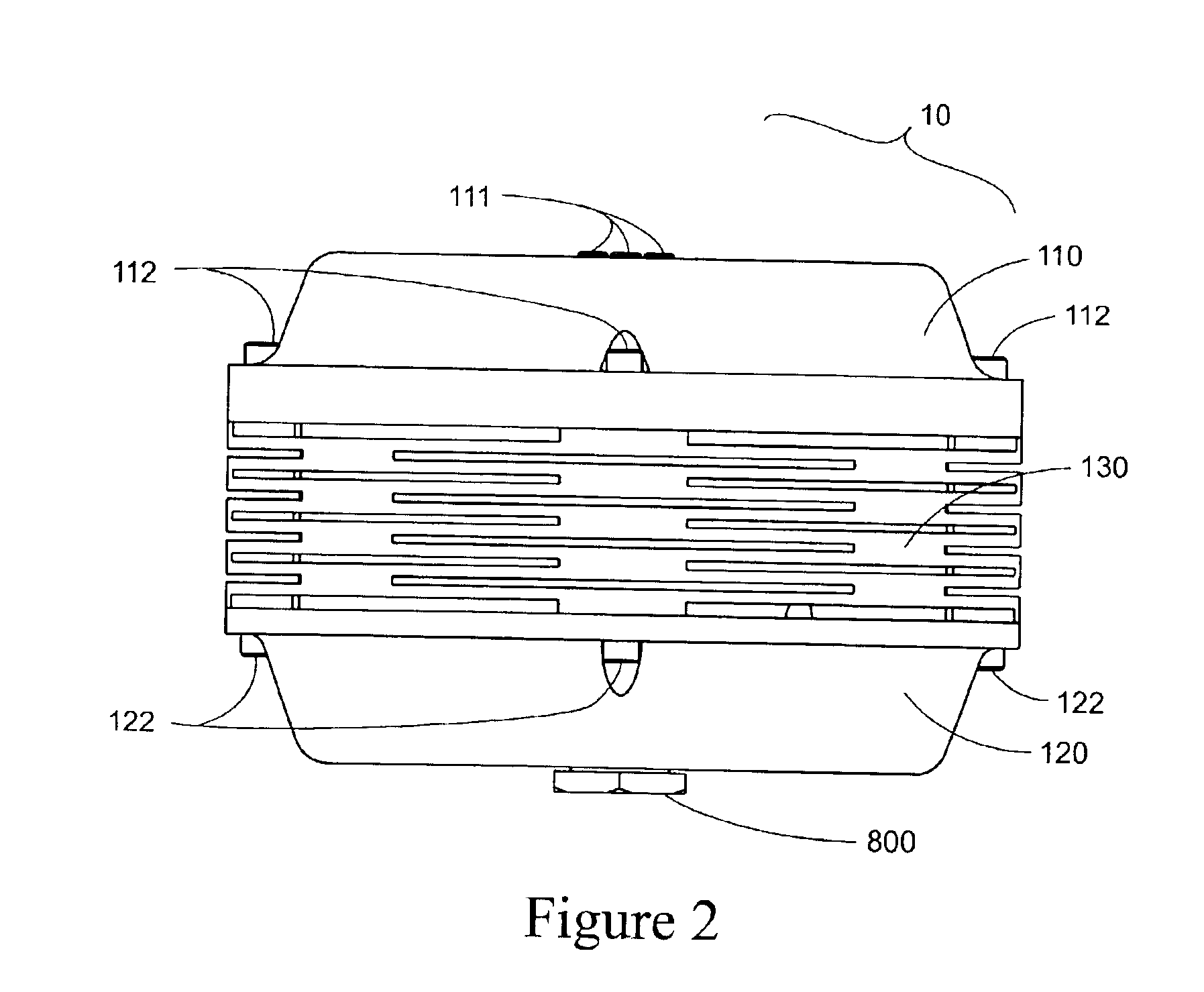
[0033]A magnetorheological fluid modulation damped vibration isolator (MRFMD isolator) 10 is depicted in isometric view in FIG. 1 and in side view in FIG. 2 in accordance with an embodiment of the invention. The exterior of the MRFMD isolator 10 is comprised of a low profile cylindrical flexure structure 130 having a top end cap 110 and bottom end cap 120 mounted at the two ends of the flexure structure.

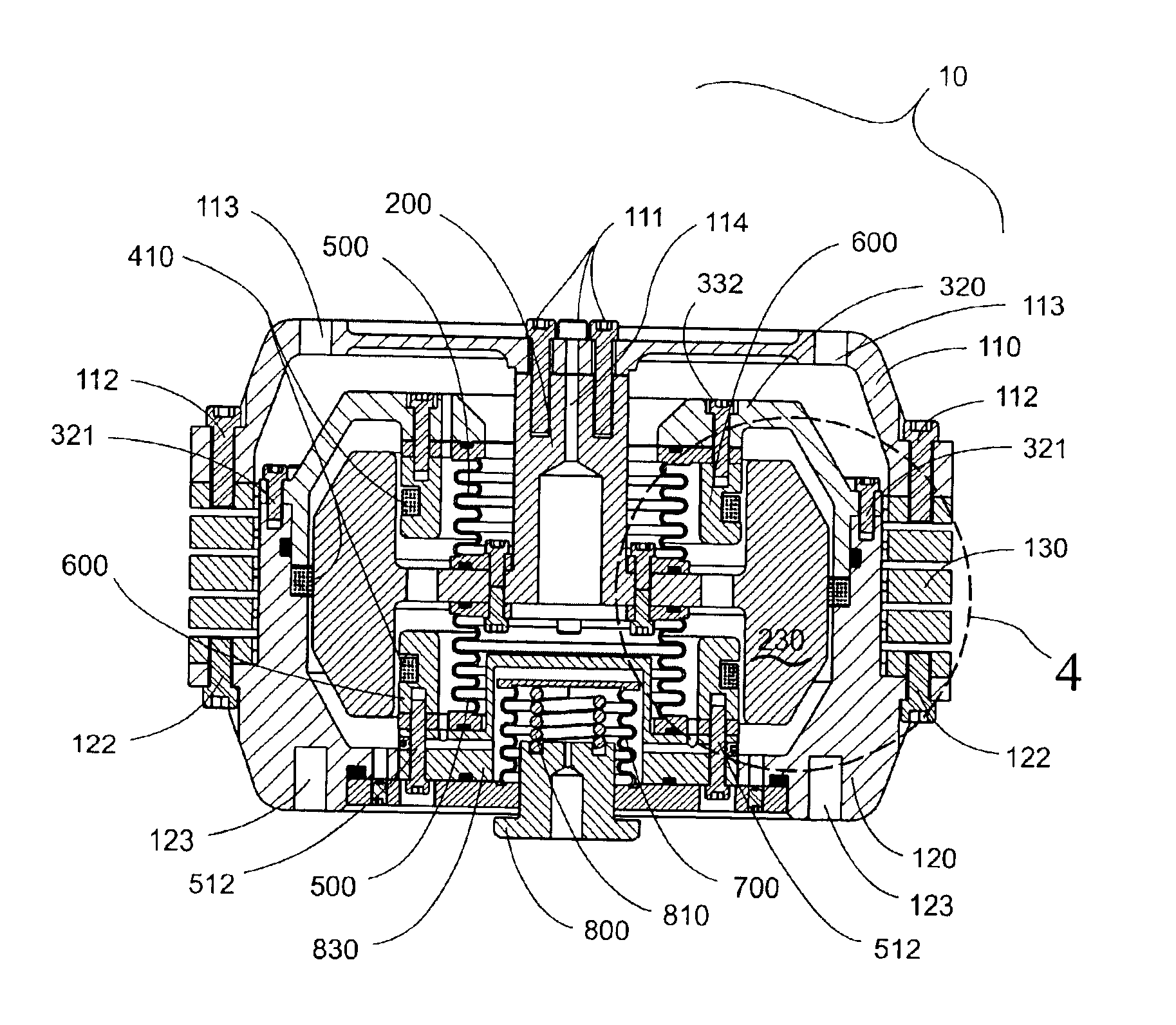
[0034]FIG. 3 shows a cross section view of the MRFMD isolator 10. The internal, damping element components and features o...


PUM


Abstract

The invention disclosed is a magnetorheological fluid device offering vibration isolation and broad modulation range damping in a high load carrying and compact form. A cylindrically shaped flexure structure has a bottom cap attached to one end and a top cap attached to the other end. A piston comprising a toroidal displacement body, a central shaft, and intermediate connecting plate, attaches to the top cap. A fluid chamber surrounding and generally conforming to the shape of the toroidal displacement body, is attached to the bottom cap. Two bellows attaching between the piston connecting plate and top and bottom portions of the fluid chamber complete an enclosed volume around the toroidal displacement body and allow frictionless motion of the toroidal displacement body relative to the fluid chamber. Electromagnetic coils placed within the inner and outer radius walls of the fluid chamber effect a magnetic field across the outer radius gap and inner radius gap between the toroidal displacement body and fluid chamber. Longitudinal deflection of the cylindrical flexure structure effects motion of the top cap relative to the bottom cap which in turn effects longitudinal motion of the toroidal displacement body within the fluid chamber. Magnetorheological fluid is forced from the top of the toroidal displacement body to the bottom, and vice-versa, across the inner radius and outer radius gaps between the fluid chamber and the inner radius of the toroidal displacement body. Static payload loads are supported with a high-strength, linear-elastic load path while base motion dynamic vibration loads are substantially isolated and damped without stiction effects.

Description

STATEMENT REGARDING FEDERALLY SPONSORED RESEARCH[0001]This invention was made with U.S. Government support under Contract No. NRO000-01-C-4374. The U.S. Government has certain royalty-free rights in this invention.BACKGROUND OF THE INVENTION[0002]The present invention relates to damping mechanisms and vibration isolation mechanisms. More particularly, the present invention pertains to a high-strength, compact, magnetorheological-fluid-modulation-damped vibration isolator.[0003]The use of magnetorheological (MR) fluid in a damping device allows for the controlled variance of device damping as a function of the strength of a magnetic field induced into a controlled or valved region of the MR fluid. Coil electromagnets, permanent magnets, or a combination of magnet types are used as the means for magnetic field creation. The use of coil electromagnets allow for the variance of the magnetic field with the variance of the electrical signal amplitude applied to the coil. Many devices exis...

Claims


Application Information

Patent Timeline
Patent Type & Authority Patents(United States)
IPC IPC(8): F16F9/53
CPCF16F9/535F16F2230/105
Inventor KELSO, SHAWN P.LINDLER, JASON E.
Owner MOOG INC
Why Eureka
Try Eureka