Method of laser capture microdissection from a sample utilizing short pulse length

Inactive Publication Date: 2005-05-24
ARCTURUS BIOSCI
View PDF24 Cites 9 Cited by
  • Summary
  • Abstract
  • Description
  • Claims
  • Application Information

AI Technical Summary

Benefits of technology

[0010]The purpose of this invention to provide a method that allows reproducible LCM transfer region of less than 20 microns with greatest precision, maximal efficiency, and minimal duration of thermal transients in the target sample caused by contact with the molten thermoplastic polymer during the laser pulse and subsequently

Problems solved by technology

In the original CO2 laser LCM designs, the use of a pressure plate (transparent and non absorbing of the laser and visi

Method used


Image

  • Method of laser capture microdissection from a sample utilizing short pulse length
  • Method of laser capture microdissection from a sample utilizing short pulse length
  • Method of laser capture microdissection from a sample utilizing short pulse length

Examples


embodiment

Preferred Embodiment

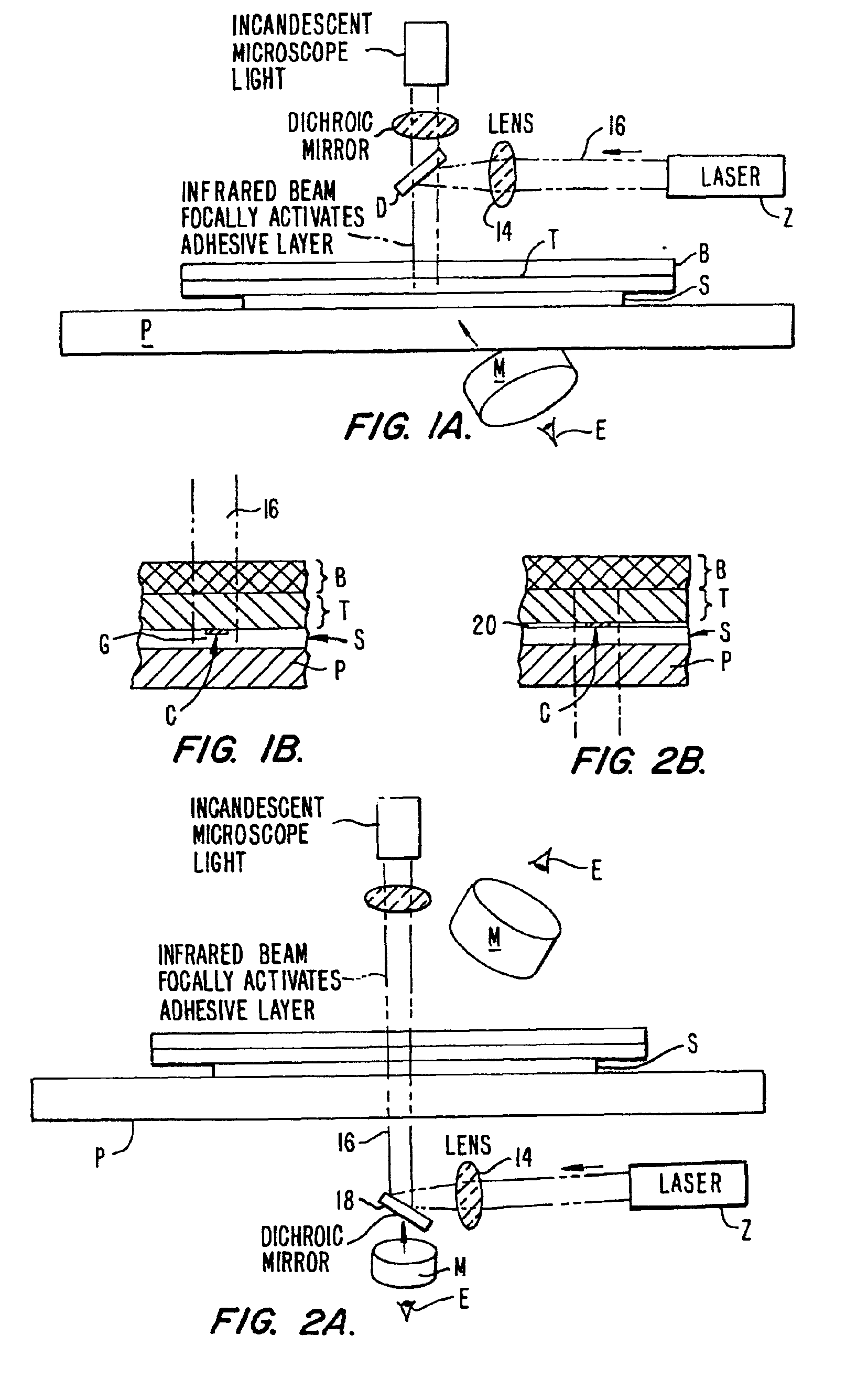
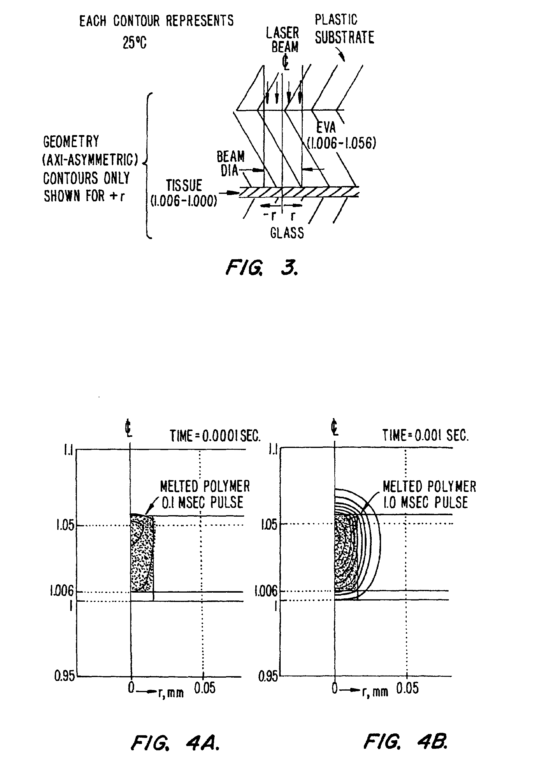
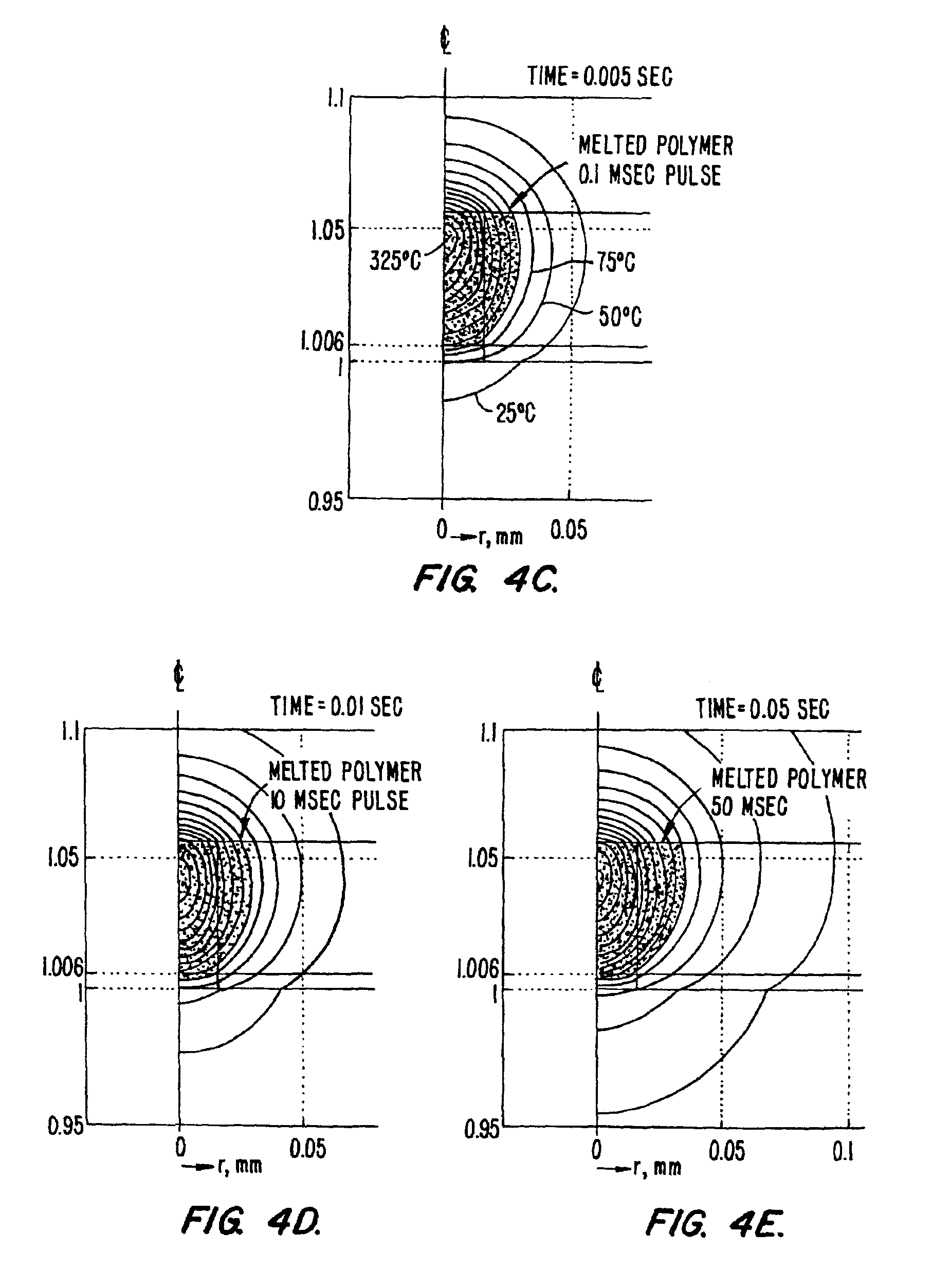
[0041]We use any of the existing LCM samples or films with any viewing or irradiation geometry [e.g., condenser side irradiation or epi-irradiation]. The combination of 1) short, small beam pulses, 2) the large fractional expansion on melting of the selected polymers (e.g., ˜10%) , and 3) the confinement of the expansion and redirection towards the target allow reliable capture of targets smaller than 10 μm. For longer pulses (as in the original CO2 case) the polymer could expand upwards as well as down and would flow by gravity of surface tension once the melted polymer made contact with the tissue (porous target). We require shorter laser pulses at somewhat higher powers than in conventional LCM in order to confine the melted volume of the attached polymer to small beam diameters (<20 microns). For these shorter pulses we require a high local pressure to force the rapid flow of polymer into the target (whether initially in contact or not). The large expansion o...


PUM

PropertyMeasurementUnit
Sizeaaaaaaaaaa
Sizeaaaaaaaaaa
Timeaaaaaaaaaa

Abstract

Laser capture microdissection occurs where the transfer polymer film is placed on a substrate overlying visualized and selected cellular material from a sample for extraction. The transfer polymer film is focally activated (melted) with a pulse brief enough to allow the melted volume to be confined to that polymer directly irradiated. This invention uses brief pulses to reduce the thermal diffusion into surrounding non-irradiated polymer, preventing it from being heated hot enough to melt while providing sufficient heat by direct absorption in the small focal volume directly irradiated by the focused laser beam. This method can be used both in previously disclosed contact LCM, non contact LCM, using either condenser-side (or beam passes through polymer before tissue) or epi-irradiation (or laser passes through tissue before polymer). It can be used in configuration in which laser passes through tissue before polymer with and without an additional rigid substrate. In its preferred configuration it uses the inertial confinement of the surrounding unmelted thermoplastic polymer (and the overlying rigid substrate) to force expansion of the melted polymer into the underlying tissue target. Utilizing the short pulse protocol, the targeted and extracted material can have a diameter equal to or smaller than the exciting beam.

Description

CROSS-REFERENCES TO RELATED APPLICATIONS[0001]This application is a continuation of U.S. application Ser. No. 09 / 495,401 filed Jan. 31, 2000, now U.S. Pat. No. 6,420,132, which is a National Stage Application of PCT / US99 / 17150 filed Jul. 28, 1999, which claims priority to U.S. Provisional Application No. 60 / 094,871 filed Jul. 30, 1998, which is incorporated herein by reference.FIELD OF THE INVENTION[0002]This invention relates to laser capture microdissection a technique wherein a specimen is visualized under a microscope and then overlaid with a layer of transfer material which when activated by a laser adheres to and extracts out specific targeted elements within the specimen for further processing. More particularly, this disclosure focuses on extracting out samples that are equal in size to or smaller than the activating laser beam. The purpose of this invention is to provide a method and apparatus for reliable microdissection of targets within tissue or other specimen samples, ...

Claims


Application Information

Patent Timeline
IPC IPC(8): G01N1/28
CPCG01N1/2813G01N2001/284G01N2001/2833
Inventor BONNER, ROBERT F.GOLDSTEIN, SETH R.SMITH, PAUL D.POHIDA, THOMAS J.
Owner ARCTURUS BIOSCI
Why Eureka
Try Eureka