Apparatus and method for detecting loss of high-speed signal

a high-speed signal and apparatus technology, applied in the field of data communication, can solve the problems of invalid or unreliable input of the receiver, waste of resources and time, and inability to detect the loss of the signal,

Inactive Publication Date: 2005-05-24
MARVELL ASIA PTE LTD
View PDF5 Cites 72 Cited by
  • Summary
  • Abstract
  • Description
  • Claims
  • Application Information

AI Technical Summary

Problems solved by technology

Unless the conductors attached at the input to the receiver are carrying a “good” serial data signal, resources and time could be wasted by the receiver processing invalid or unreliable input.
A “bad” signal can also occur if the signal conductors become damaged or temporarily interrupted.
At such times, the signal appearing on the conductors at the input to the receiver can become invalid or not reliable, appearing random, having significantly reduced amplitude, or having both signal conductors stuck at the voltage supply level (a “stuck-at-high” fault).
When loss-of-signal occurs, some types of receivers that are equipped with a decision feedback equalizer (“DFE”) feature may attempt inappropriately to locate the signal by increasing the gain at the receiver's front end.
However, the system disclosed in that article is not robust, possibly falsely detecting a good signal when a voltage or current spike appears, and having difficulty detecting valid signals in systems having a serial data transmission rate of 5 Gbs and higher.
A disadvantage of the system described in the '082 patent is that it cannot proceed without having recovered a good clock from the input data signal at the beginning of a data communication period.
However, if the input signal is bad from the beginning, the clock may not be present or may be unreliable and incapable of accurately sampling the input signal, making the loss-of-signal detector fail to work at all.
Another problem of the system described in the '082 patent is that it only permits a fixed signal threshold level setting for detecting loss-of-signal.
As a result, in communication systems using SerDes cores, a good signal threshold for one system can sometimes resemble noise in others.
As in the above system described in the '082 patent, this system also cannot operate over the wide range of signal frequencies and voltage levels that are desirable for SerDes cores.

Method used


Image

  • Apparatus and method for detecting loss of high-speed signal
  • Apparatus and method for detecting loss of high-speed signal
  • Apparatus and method for detecting loss of high-speed signal

Examples


Embodiment Construction

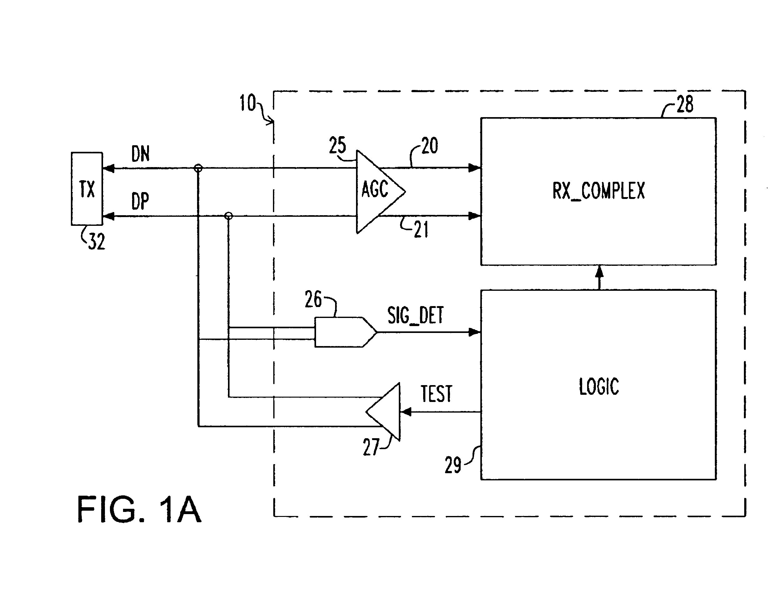
[0029]FIG. 1A is a block and schematic diagram illustrating interconnection and use of a signal detector 26 according to an embodiment of the invention. As shown in FIG. 1A, a high speed serial signal is input to a receiving end 10 of a serial link as a difference signal between the voltages on a pair of differential signal lines (conductors) DN and DP. The differential signal on the pair of differential signal lines DN and DP is amplified to a predetermined reception level by an automatic gain controlled amplifier (AGC) 25. Thereafter, the output of the AGC 25 is input to a receiver complex 28 via lines 20 and 21, where the amplified signal is then quantized and sampled with a clock recovered from the input signal to capture the data carried by the signal.

[0030]The input signal on the pair of differential signal lines DN and DP is also input to a signal detector 26, which provides an output SIG_DET to logic block 29 to signal the presence or absence of the differential input signal...


PUM


Abstract

An apparatus and method is provided for detecting loss of differential signal carried by a pair of differential signal lines. According to the method, a common mode level is detected from voltages on the pair of differential signal lines. A threshold level is generated, referenced to the detected common mode level. A signal level is generated from the voltages on the pair of differential signal lines, the signal level being averaged over a first period of time. From the threshold level and the detected common mode level a reference level is generated, the reference level being averaged over a second period of time longer than then the first period of time. The signal level is compared to the reference level to determine if a signal is present on the pair of differential signal lines.

Description

BACKGROUND OF INVENTION[0001]The present invention relates to data communications, and more specifically to an apparatus and method for detecting loss-of-signal in a serial data communications system.[0002]In contemporary high-speed serial data communications, a duplex high-speed serial (HSS) communication link is typically implemented by an integrated circuit (“IC” or “chip”) that includes at least one pair of a serializer (transmitter) and a deserializer (receiver) on the same chip. Such elements can also be provided in the core of a multi-function chip, such core being referred to as a serializer—deserializer (SerDes) core. At a transmitting end of a serial link, the transmitter of a SerDes core takes a set of parallel data signals at a moderate switching speed and converts them to a high switching speed serial signal for transmission to a remote receiver. At the remote end of the link, another SerDes core receives the high switching speed serial signal and deserializes it back i...

Claims


Application Information

Patent Timeline
Patent Type & Authority Patents(United States)
IPC IPC(8): G05F1/10H03K5/22H03K5/08H03K5/19H04L25/02H04L25/08
CPCH03K5/08H04L25/085H03K5/19H04L25/0272
Inventor FICKEN, WESTERFIELD J.HSU, LOUIS L.MASON, JAMES S.MURFET, PHIL J.
Owner MARVELL ASIA PTE LTD
Why Eureka
Try Eureka