While conventional forms of
glazing serves many useful functions, such forms are not without problems.
The energy transmitted through the
glass window is typically absorbed by furnishings or structures within the interior environment, and often becomes trapped therewithin causing an increase in interior temperature.
However, as window blind is mounted within the interior of the building or transportation environment, electromagnetic
radiation is allowed transmit through the window, raises the temperature within the internal environment, and thus increases thermal loading on cooling systems during the
hot weather season.
Also, the operation of window blinds requires mechanical or electro-mechanical controls which tend to be bulky and expensive to manufacture, install and maintain.
The major disadvantages thereof are reduction in interior light, loss of
visibility, and extra care required in cleaning.
Moreover, prior art electromagnetic window films are incapable of changing from transmissive during winter months to reflective during summer months in order to effectively use electromagnetic
radiation for dynamic
temperature control of biological environments (e.g. human habitats, greenhouses and the like).
Consequently, during heating seasons, such glass fails to lessen the thermal loading on the heating systems of such buildings, as would be desired in an effort to conserve energy and heating resources during the winter months.
This, however, results in high optical loss, as up to 60% of the incident light is absorbed by the polarizers, in the desired non-blocking mode of operation.
While a smart window
structure based on
polymer dispersed
liquid crystal (PDLC) technology offers better performance than TN or STN based window structures, such smart window structures suffer from several significant shortcomings.
However, the electrochromic device suffers from
slow response time and shorter life-time.
However, this technology has a problem associated with the
settling of the
metal particles due to gravity.
The second problem associated with prior art PDLC technology is its high cost of manufacture.
Due to the extremely high price of manufacture, such manufacturers are facing significant obstacles in expanding the PDLC privacy window market.
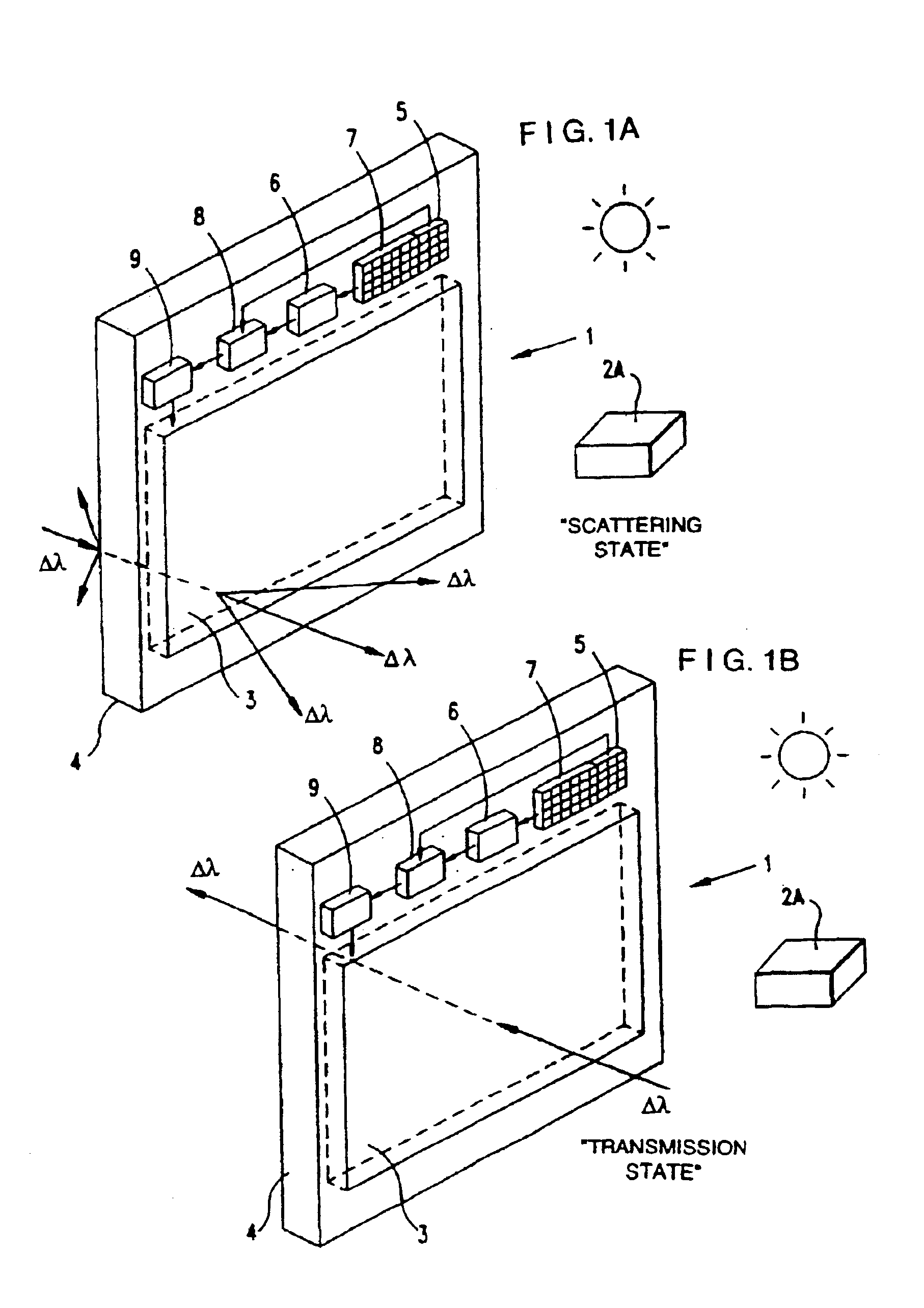
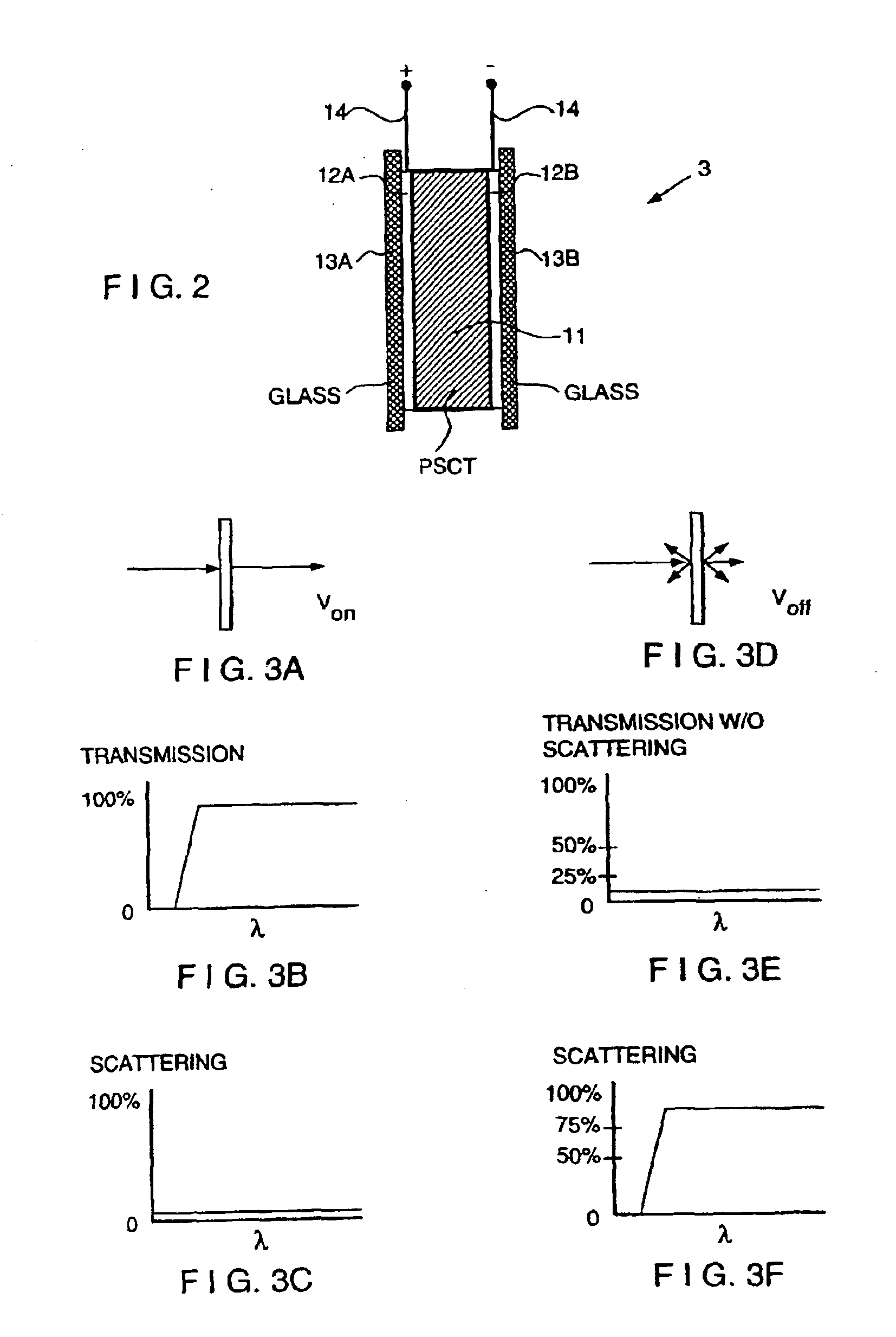
Prior art PSCT technology has at least five significant problems which hitherto have neither been addressed or solved in a satisfactory manner.
Therefore, the cost of such a
liquid crystalline polymer becomes extremely high, making the price of the PSCT device even higher than that of the PDLC.
Secondly, in typical PSCT systems, since monomers with mesogenic groups are used, the formation of the
polymer network will partially alter the orientational order at each cross-linking site.
Such a field often brings about electric shorting problems.
However, the
liquid crystal molecules close to the
polymer network will not respond to a modest switching field, resulting in strong
haze, particularly at large oblique angles.
Thirdly, scaling-up the panel size of PSCT-based devices has been very difficult in practice.
Fourthly, making a large-size uniform PSCT device is difficult because this lamination method cannot be used.
Therefore, the resulting PSCT device appears very non-uniform.
Finally, the cost of glass substrates with conductive
Tin Oxide layer coatings is very expensive when using PSCT-based technology.
Also, the cost of plastic substrates with conductive
Tin Oxide layer coatings is very expensive when using PDLC technology.
Such factors contribute to the high price of electro-optical devices based on PDLC and PSCT technologies.



