Transmission line capacitor

Inactive Publication Date: 2005-05-24
AVX CORP
View PDF30 Cites 22 Cited by
  • Summary
  • Abstract
  • Description
  • Claims
  • Application Information

AI Technical Summary

Benefits of technology

[0015]Another principal object of the present subject matter is to provide a transmission line capacitor that offers both biasing function

Problems solved by technology

However, transmission lines are not only utilized in large-scale environments; in fact, even the smallest electrical applications often employ transmission line configurations for energy distribution.
However, high-frequency signals traveling in such a fashion may be readily susceptible to a variety of undesirable signal-altering phenomena, including nois

Method used


Image

  • Transmission line capacitor
  • Transmission line capacitor
  • Transmission line capacitor

Examples


embodiment 30

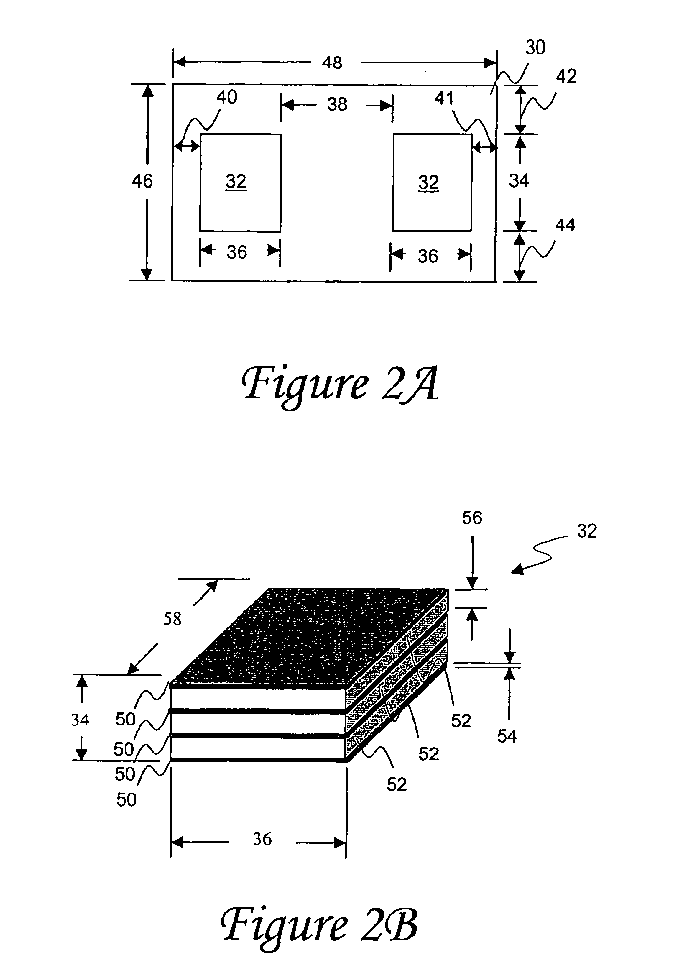
[0048]Assume that it is desirable to have a characteristic impedance of about 100 Ω and for the dielectric material between capacitors 32 in embodiment 30 of FIG. 2A to be characterized by a dielectric constant of about 8.1. Utilizing the characteristic impedance formulas given in (1), it is thus determined that for the above exemplary performance characteristics it is desired to have a height to spacing ratio (distance 34 / distance 38) of about 0.313. FIG. 3A provides a graphical representation of the relationship between the height to spacing ratio versus dielectric constant for a transmission line capacitor as depicted in FIG. 2A and having a given characteristic impedance of 100 Ω. Some particular examples of this relationship are given in Table 1 below.

[0049]

TABLE 1Exemplary Values for Design of First TransmissionLine Capacitor EmbodimentHeight to Spacing RatioDielectric Constant (εr):(distance 34 / distance 38):1.02.4762.71.3388.10.31315.0 0.130

exemplary embodiment 30

[0050]When designing a transmission line capacitor embodiment such as first exemplary embodiment 30, it should be noted that the height and spacing are particularly important design aspects of such device. Thus, it is important also to account for the fact that the height 34 of each capacitor 32 includes not only the thickness of the dielectric material, but the thickness of each active conductive plate within the capacitor. It was previously mentioned that capacitor 32 may be characterized by a plurality of active plates connected together in parallel to yield respective multilayer capacitors. This is represented by the perspective depiction in FIG. 2B of an exemplary embodiment of a capacitive element 32 in transmission line capacitor 30. Multilayer capacitor 32 is preferably formed with a plurality of active electrode layers 50 separated by layers of dielectric material 52. Three dielectric layers 52 are illustrated in FIG. 2B for exemplary purposes only. It should be appreciated...

embodiment 60

[0059]For exemplary calculation purposes, assume that ∈r1=100.0 and that ∈r2=1.0. If a value of ∈r=10 is desired, then (3) can be solved to determine that distance 70 needs to be 0.273 mm. Similarly, if a value of ∈r=20 is desired, then (3) can be solved to determine that distance 70 needs to be 0.242 mm. FIG. 4B provides a graphical representation of the equivalent dielectric constant (∈r) versus cut-width for embodiment 60 of FIG. 4A assuming that ∈r1=100.0 and that ∈r2=1.0.

[0060]The exemplary numerical analysis presented above with respect to the second transmission line capacitor embodiment 60 is provided merely as an example of how to form a transmission line capacitor embodiment having a channel portion formed therein in accordance with the present technology. It should be noted from the exemplary data that the channel area needs to be cut quite precisely in order to ensure a given equivalent dielectric constant (∈r) between capacitors 62. Thus, it may be preferred to fill the...


PUM

PropertyMeasurementUnit
Electric impedanceaaaaaaaaaa
Dielectric polarization enthalpyaaaaaaaaaa
Electric potential / voltageaaaaaaaaaa

Abstract

A transmission line capacitor includes at least two side-by-side capacitor portions spaced apart between a separating portion all contained in a single monolithic body. Such transmission line capacitors provide specific capacitor functionality for parallel transmission lines in a printed circuit board environment, while also maintaining a desired impedance value between the transmission paths. The transmission line capacitors offer both biasing functionality for blocking undesired DC voltages as well as AC coupling functionality for passing AC voltage signals with preserved data integrity. A first embodiment may be formed with a dielectric material having a relatively low dielectric constant, allowing high capacitor “height” with fixed spacing between distinct capacitive structures. Another embodiment may be formed with a relative high K dielectric and then slotted with an air gap between capacitive structures. Yet another embodiment may be formed with a relatively high K dielectric material, and with a relatively low K material provided in between capacitive structures. A still further embodiment concerns a transmission line capacitor design formed with high K and low K dielectric materials punched into a monolithic thin-film device.

Description

PRIORITY CLAIM[0001]This application claims the benefit of previously filed U.S. Provisional Patent Application entitled “Transmission Line Capacitor,” assigned U.S. Ser. No. 60 / 434,930, filed Dec. 19, 2002, and which is incorporated herein by reference for all purposes.BACKGROUND OF THE INVENTION[0002]The present subject matter generally concerns a coupling capacitor for use in conjunction with components and signal connections in a printed circuit board (PCB) environment. At least two capacitor structures are provided in a single monolithic device to form a transmission line capacitor in accordance with the present subject matter.[0003]A transmission line is generally defined as two or more parallel conductors used to connect a source to a load. Such terminology often conjures thoughts of power generation and distribution systems that utilize large-scale transmission lines to transport electrical energy among multiple sources and loads of a power network. However, transmission lin...

Claims


Application Information

Patent Timeline
IPC IPC(8): H01G2/00H01G2/06H01G4/08H01G4/35H01G4/30H01G4/18H01G4/018H01G4/38H01G4/228H01G4/02H01G4/12H01G4/14H01G4/232
CPCH01G4/232H01G4/38H01G4/30
Inventor KORONY, GEORGERITTER, ANDREW P.
Owner AVX CORP
Why Eureka
Try Eureka