System for latching an output signal generated by comparing complimentary strobe signals and a data signal in response to a comparison of the complimentary strobe signals

a technology of output signal and complementary strobe, which is applied in the field of electronic circuit technology, can solve the problems of signal (dout), unfavorable high-speed i/o bus applications, and the disadvantages of conventional data comparators, and achieve the effect of preventing erroneous sampling

Active Publication Date: 2005-05-24
VIA TECH INC
View PDF8 Cites 104 Cited by
  • Summary
  • Abstract
  • Description
  • Claims
  • Application Information

AI Technical Summary

Benefits of technology

[0009]Therefore, the objective of the present invention is to provide a data transmission system which utilizes a pair of complementary signals as a reference voltage of the data comparator to overcome the drawbacks of the conventional p

Problems solved by technology

However, both of the conventional data comparators still suffer from some drawbacks.
In the pseudo-differential scheme, the slew rate of the data signal (DATA) and the variation of the reference voltage (VREF) will affect the output timing of the output signal (DOUT), which is unfavorable to the applications of high-speed I/O buses.
In the fully differential scheme, every data signal requires two pins to send the original and its inverse signal, which can

Method used


Image

  • System for latching an output signal generated by comparing complimentary strobe signals and a data signal in response to a comparison of the complimentary strobe signals
  • System for latching an output signal generated by comparing complimentary strobe signals and a data signal in response to a comparison of the complimentary strobe signals
  • System for latching an output signal generated by comparing complimentary strobe signals and a data signal in response to a comparison of the complimentary strobe signals

Examples


Embodiment Construction

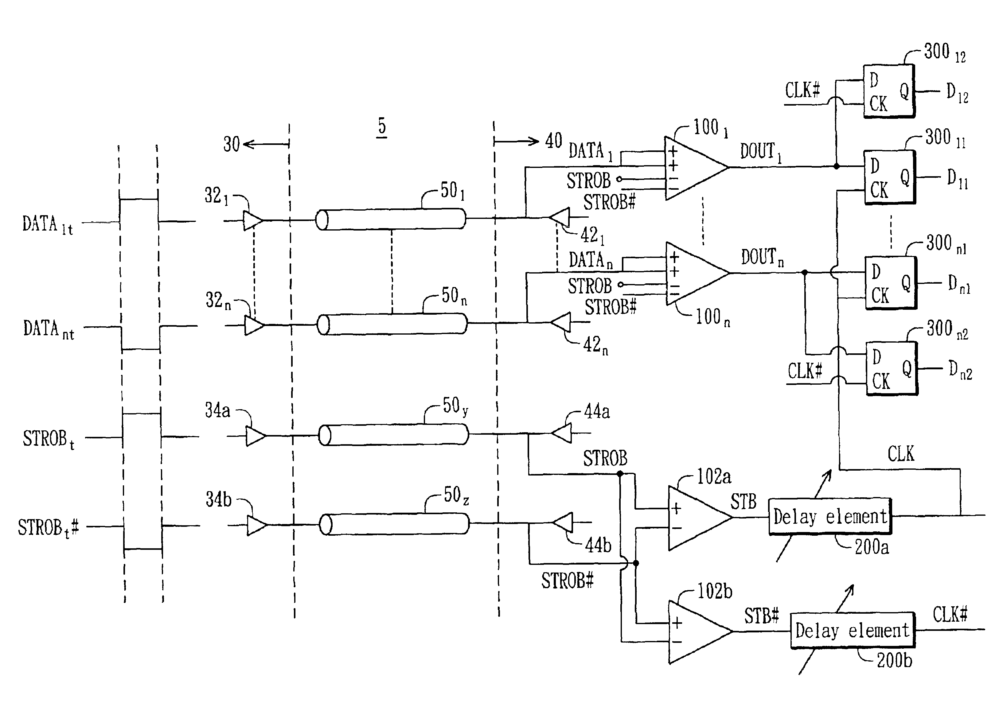
[0022]The present invention discloses a novel data transmission system, which employs a pair of complementary signals as an edge-aligned strobe signal and its input / output buffers. The novel data transmission system uses the same structure of the output circuits and the I / O pads designed for the transmission of the data signals to transmit the pair of complementary signals, the falling / rising edges of which are aligned with those of the data signals. The pair of complementary signals are used to substitute for the conventional constant reference voltage, thereby solving the drawback of the conventional pseudo-differential scheme and the conventional fully differential scheme. As well, at the receiver, a delay element is inserted and used to compensate for the skew amount in the transmitted data signals.

[0023]The data transmission system of the preferred embodiment of the present invention is described as follows. FIG. 3 is a block diagram of the data transmission system 5 according ...


PUM


Abstract

A data transmission system using a pair of complement signals (STROB/STROB#) as an edge-aligned strobe signal and input/output buffers therein. Several data signals and a pair of STROB/STROB# signals are transmitted from a data output device to a data input device therein. These data signals and the STROB/STROB# signals are edge-aligned and transmitted through the same transmission architecture. The data input device includes several data comparators for generating output signals from the received data signals using the received STROB/STROB# signals as a dynamic reference voltage. In addition, the data input device further includes several comparators and delay elements for generating a pair of non-inverting/inverting latch clock signals from the STROB/STROB# signals. Each of the output signals is sent to two data latch circuits for outputting two latched data based on the latch clock signals.

Description

[0001]This application claims the benefit of U.S. provisional No. 60 / 291,253 filed May 15, 2001.BACKGROUND OF THE INVENTION[0002]1. Field of the Invention[0003]The present invention relates to an electronic circuit technology, more specifically, to a data transmission system using a pair of complementary signals as an edge-aligned strobe signal and input / output buffers therein.[0004]2. Description of the Prior Art[0005]Conventional high-speed input / output buses employ a pseudo-differential scheme or a fully differential scheme to restore small swing signals back to full swing of logic “1” or “0.” These data will be latched by synchronous clocks or strobe signals sent from the transmitter. The difference between the pseudo-differential data comparator and the fully differential data comparator is described as follows.[0006]FIGS. 1A and 1B (Prior Art) are a circuit diagram and a timing diagram of the conventional pseudo-differential data comparator, respectively. As shown in the figur...

Claims


Application Information

Patent Timeline
IPC IPC(8): H04L7/033H04L7/00G06F13/40H03K19/0175
CPCG06F13/4072H04L7/0337H04L7/0008
Inventor CHANG, CHI
Owner VIA TECH INC
Why Eureka
Try Eureka