Method and apparatus for production of droplets

a technology of droplets and atomization, which is applied in the direction of lighting and heating apparatus, heating types, separation processes, etc., can solve the problems of high velocity of emerging droplets, inability to control the size and quantity of emerging droplets for a specific nozzle design, and inability to eliminate some other deficiencies inherent in the process, etc., to achieve control the atomization performance, low velocity, and simple operation

Inactive Publication Date: 2005-05-31
ULTRASONIC DRYER +1
View PDF16 Cites 10 Cited by
  • Summary
  • Abstract
  • Description
  • Claims
  • Application Information

AI Technical Summary

Benefits of technology

[0043]Still further object of the invention is to provide a new and improved method and device for atomizing of liquids, in which it is possible to produce large amount of ultra-fine droplets, emerging with low velocity and in which it is possible to control the atomization performance without deteriorating the droplets size distribution.
[0044]Another object of the invention is to provide a new and improved device for atomizing of liquids, which is suitable for use as nebulizer, which is simple in operation, which is inexpensive and which operates reliably without clogging.SUMMARY OF THE INVENTION
[0045]The atomizing device of invention can be attributed as a pneumatic sprayer. Due to the low travel velocity of droplets emerging from the device it combines the advantages of ultrasonic sprayers, however in contrast to them, it does not heat the atomizing liquid, but cools it. This feature makes the present invention extremely advantageous in medical applications and in pneumatic sprayers, because of simplicity and low production costs.

Problems solved by technology

Despite there are known some attempts to overcome this major shortcoming, nevertheless, these attempts do not eliminate some other deficiencies inherent to the above-mentioned atomizing devices.
2. In the case of pneumatic nozzles:Necessity in high gas pressure (4-7 atmospheres), which causes higher velocity of emerging droplets;Danger of contamination due to the small outlet diameter (0.2-0.4 mm), or due to strict tolerance for the dimension of the outlet slit for compressed gas;High consumption of the compressed gas per mass unit of sprayed liquid;Impossibility to control droplets size and quantity for a specific nozzle design.
3. In the case of disk atomizers:High cost of the spraying device;Necessity of careful maintenance, including greasing and monitoring of disk condition;Danger of imbalance due to high disk rotation speed (20,000 rev / min and above) causing thermal expansion of disk material and, as a result, larger outlet dimensions;High velocity of emerging droplets (140 m / sec and more), resulting in a larger distance of flight and thus larger diameter of spray;Ventilation effect due to high disk rotation velocity, which creates low pressure above the disk and affects the configuration of the spray and the flight distance of the droplets;Impossibility to control the droplets size and their amount at a given disk diameter and rotation speed.
4. In the case of ultrasonic sprayers:High cost of device;Low reliability;Strong dependence on viscosity and surface tension of the sprayed liquid;Liquid heating, which affects its properties and, therefore, may not always be permitted;Limited capacity.
Nevertheless, all these solutions failed to overcome such disadvantages as contamination, reduced performance, subsequent clogging up of the outlets and an undesirable high velocity of droplets.

Method used


Image

  • Method and apparatus for production of droplets
  • Method and apparatus for production of droplets
  • Method and apparatus for production of droplets

Examples


example 1

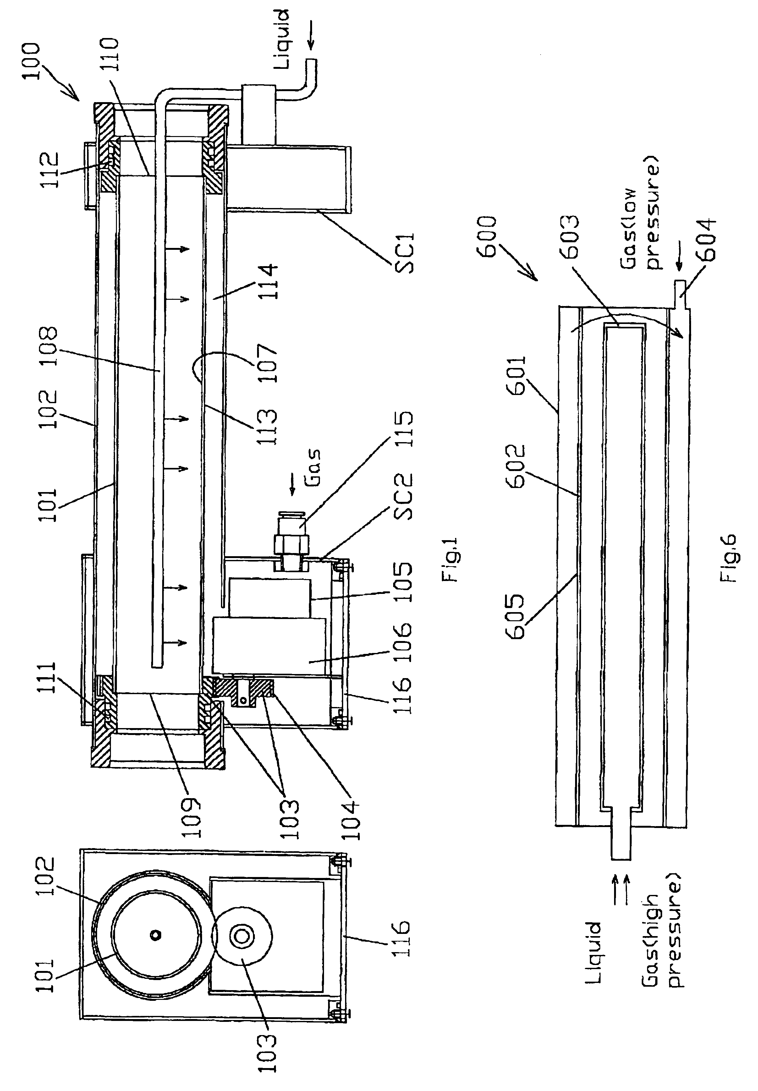
[0079]As seen in FIG. 1 a sprayer 100 is positioned horizontally and is formed as a double-wall tubular body, supported at both ends by supporting columns SC1 and SC2. The inner wall of the sprayer body comprises an internal porous gas-permeable cylinder 101 and the external wall of the body comprises an external gas-impermeable cylinder 102. The internal gas-permeable cylinder resides concentrically inside the external cylinder with possibility for rotation along its longitudinal axis. Rotation can be effected for example by virtue of a tooth wheel 103, rigidly secured on the internal cylinder. The tooth wheel interacts with a pinion 104, which is driven by a motor 105 through a set of pinions 106. An inner surface 107 of the internal cylinder is moistened by a liquid delivered thereto from an external source (not shown) via a perforated pipe 108, extending along the longitudinal axis of the internal cylinder. In order to wet the entire inner surface of the internal cylinder it is ...

example 2

[0086]The sprayer in accordance with this embodiment is shown in FIG. 2. This embodiment is designated by numeral 200 and its configuration basically is similar to the embodiment designated by numeral 100, i.e. it includes permeable cylinder 201, disposed horizontally. The cylinder is secured with possibility for rotation along its longitudinal axis by virtue of a motor 202, a set 203 of pinions, a pinion 204 and a toothed wheel 205. The permeable cylinder resides in the upper part of an elongated housing, which is defined by an upper cover 206, by opposite lateral walls 207,208, by front and rear walls (not shown) and by a flat bottom 209. The permeable cylinder is mounted in the lateral walls of the housing with the aim of sealing flanges. A hollow space 210 is provided within the lower part of the housing under the permeable cylinder. A perforated pipe 211 delivers a liquid from an external source (not shown) to an inner surface 212 of the permeable cylinder. An air-pumping means...

example 3

[0088]With reference to FIG. 3 the sprayer 300 according to this embodiment consist essentially of the same elements and has the same configuration as the sprayer disclosed in Example 1. It can be seen, that the sprayer is directed horizontally and is supported by supporting columns. Compressed gas is delivered to the sprayer via inlet port provided in one of the columns. The sprayer comprises an internal permeable cylinder 301, which is disposed within and co-axially with an external impermeable cylinder 302. However in contrast to the previous embodiments here the internal porous cylinder is rigidly secured within the external cylinder and therefore does not rotate. An inner surface 303 of the porous cylinder is moistened by virtue of a sprinkle means 304, which is formed as rotating disk, provided with tangentially disposed nozzles to which a liquid is delivered from an external source (not shown) via a tube 305, made of elastic material. The sprinkle means is connected to one en...


PUM

PropertyMeasurementUnit
flow rateaaaaaaaaaa
pressureaaaaaaaaaa
thicknessaaaaaaaaaa

Abstract

The invention concerns a method and apparatus (100) for producing mist of a liquid phase having very fine and mono-dispersed droplets. The method is realized by an apparatus (100) including a partition (101), defined by a first side surface (107) and a second side surface (113). The first side surface (107) is wetted by a liquid phase to form a film thereon, while the second side surface (113) is substantially dry. A gas stream is directed through the partition (101) from the dry side (113) to the wetted side (107) thereby forming a mist having droplets of less than 1 micron in size and a concentration of at least 1,000,000,000,000 per cubic cm.

Description

[0001]This application claims the benefit of prov. application No. 60 / 262,032 filed on Jan. 18, 2001.BACKGROUND OF THE INVENTION[0002]1. Field of the Invention[0003]The present invention relates to the field of liquid atomization and in particular to the large-scale production of ultra-fine, homogenous liquid droplets or aerosols, emerging with low velocity.[0004]The invention is also related to an apparatus for large-scale production of a mist, consisting of ultra-fine homogenous liquid droplets or aerosols, which employs the above method of liquid atomization.[0005]2. Description of the Prior Art[0006]In the further description the terms atomization and atomizer refer to the process and device, in which is achieved complete destruction of a jet of an incompressible liquid and a mist, consisting of poly-disperse drops is produced. The apparatuses, employing atomization for producing of ultra-fine droplets are known in the art as nebulizers.[0007]There are known various methods and ...

Claims


Application Information

Patent Timeline
Patent Type & Authority Patents(United States)
IPC IPC(8): B05B7/00F02M29/00B05B7/24B05B17/04F28C3/06
CPCB05B7/0012B05B7/2483B05B17/04F28C3/06Y10S261/65Y10S261/25F02M29/00
Inventor SADYKHOV, AKPER
Owner ULTRASONIC DRYER
Why Eureka
Try Eureka