Jacket frame floating structures with buoyancy capsules

a floating structure and anchor frame technology, applied in the field of offshore floating structures, can solve the problems of inability to produce dry-tree oil, limited stability, and high center of gravity of the entire semi-submerged vessel, and achieve the effect of large deck area and efficient respons

Inactive Publication Date: 2005-05-31
SRINIVASAN NAGAN
View PDF16 Cites 46 Cited by
  • Summary
  • Abstract
  • Description
  • Claims
  • Application Information

AI Technical Summary

Benefits of technology

[0025]It is therefore an object of the present invention to provide an offshore jacket column stabilized floating structure having buoyancy capsules enclosed within an open cross-braced jacket framework or truss support structure that can economically support a large deck area in deepwater and responds efficiently to environmental forces in ultra-deepwater.

Problems solved by technology

The center of gravity of the entire semi-submersible vessel is generally high due to large deck loads above the water.
A semi-submersible vessel is sensitive to the variable deck loads and its stability is limited.
Semi-submersibles have large heave motions (vertical oscillation of the floating vessel) when subjected to waves and consequently a dry-tree oil production system is not feasible.
In the case of a drilling semi-submersible, downtime of drilling may occur when the heave motion is not feasible for drilling.
Secondly, the size of the lower hull increases the economics to always maintain tension in the tendons with respect to the increased water depth.
However, the SPAR has limitations in deck area and payload due to its size.
Ultra deepwater posses problems to the riser tensioning system and limits the applicability of the SPAR.
Mooring of the SPAR in deepwater over 5000 ft. also posses a serious problem.
The SPAR also poses vortex shedding vibration problems when the vertical single column hull becomes extremely slender.
Typically, the SPAR hull vertical caisson structure is built in a Far East or European shipyard due to inadequate fabrication facilities in United States shipyards.
The cost and time involved in the fabrication and transportation of the hulls are significant in the project of an offshore oil production development, and in some marginal production fields, the conventional fabrication and transportation process is not time and cost effective.
These types of thin walled stiffened shells are susceptible to fracture and crack propagation that might lead to large catastrophic failure.
Thus, the maintenance cost is increased for the shell-type hull floating vessels.

Method used


Image

  • Jacket frame floating structures with buoyancy capsules
  • Jacket frame floating structures with buoyancy capsules
  • Jacket frame floating structures with buoyancy capsules

Examples


Embodiment Construction

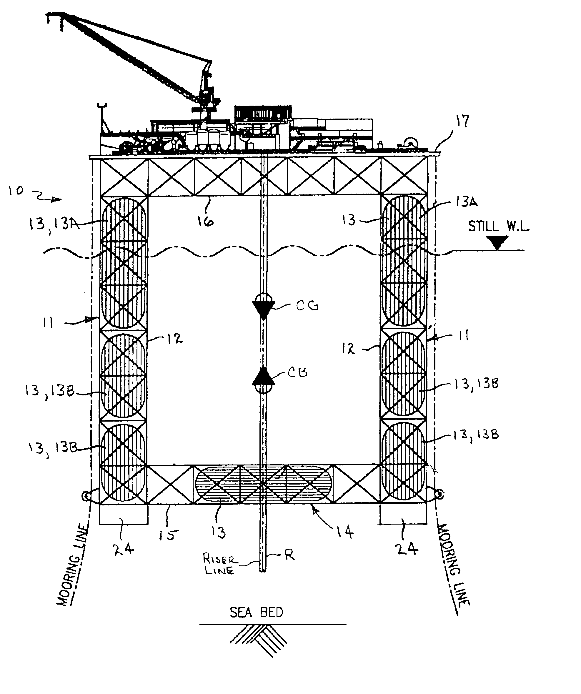
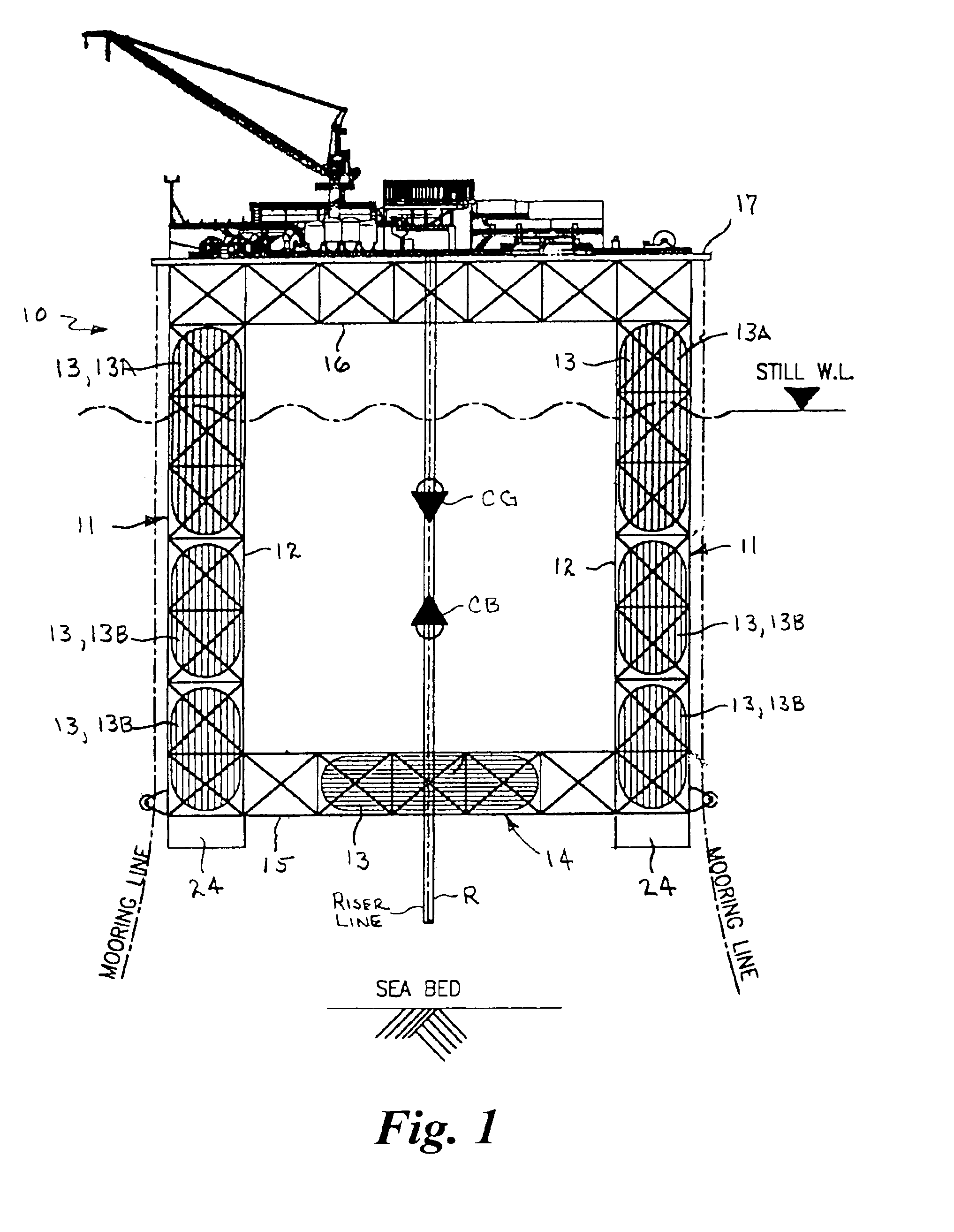
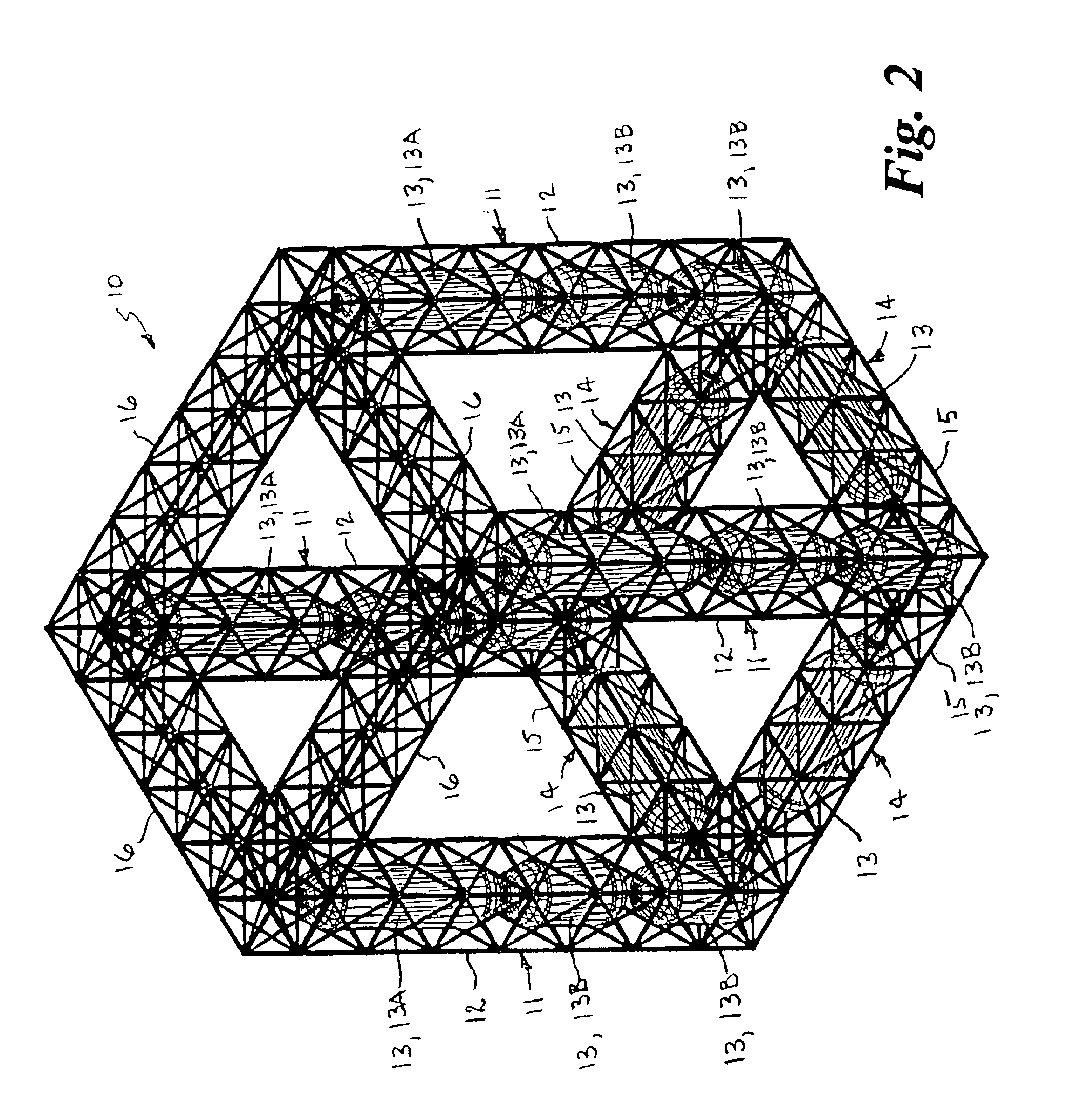
[0045]Referring now to FIGS. 1 and 2, there is shown, somewhat schematically, a column stabilized semi-submersible floating offshore drilling and production platform structure 10 having vertical columns 11 formed of open cross-braced jacket frames 12 with vertically spaced buoyancy capsules 13 enclosed therein and horizontal truss pontoons 14 formed of open cross-braced trusses 15 with buoyancy capsules 13 enclosed therein in accordance with the present invention. The column stabilized floating structure is similar to a semi-submersible platform and may have three or more jacket frame columns 11 interconnected at their lower ends with the open cross-braced pontoon trusses 15. In this example, the upper ends of the vertical jacket frame columns 11 are shown interconnected with horizontal open cross-braced deck support trusses 16, and a deck 17 is supported thereon. It should be understood that a conventional deck of plate construction having one or more levels may be secured to the u...


PUM


Abstract

Jacket frame floating structures comprise one or more elongate vertical support columns formed of an open cross-braced jacket formwork of tubular members interconnected together and at least one cylindrical buoyancy capsule disposed in the open framework near an upper end and at least one cylindrical second buoyancy capsule near a lower end in vertically spaced relation. The buoyancy capsule(s) may be a single, or a plurality of upper and lower capsules bundled in circumferentially spaced relation with a central opening therethrough. Alternatively, a keel tank may replace the lower capsule. The buoyancy of the upper buoyancy capsule(s) is adjustably tuned to provide a buoyant force and a sufficient water plane area and moment of inertia required for stability of the floating structure, and the water mass and weight of the lower buoyancy capsule(s) or keel tank(s) is adjustably tuned to raise or lower the center of gravity of the entire mass of the floating structure with respect to its center of buoyancy according to ballast and variable or fixed loads including deck payloads to stabilize the structure. Alternatively, a keel tank may replace the lower capsule. The buoyancy of the upper buoyancy capsule(s) is adjustably tuned to provide a buoyant force and a sufficient water plane area and moment of inertia required for stability of the floating structure, and the water mass and weight of the lower buoyancy capsule(s) or keel tanks(s) is adjustably tuned to raise or lower the center of gravity of the entire mass of the floating structure with respect to its center of buoyancy according to ballast and variable or fixed loads including deck payloads, to stabilize the structure, and to compensate for different operational, environmental, survival and installation stages of the structure. The length of the upper buoyancy capsule(s) is sufficient so as to be partially submerged and allow oscillation of the trough and crest of waves within its top and bottom ends.

Description

CROSS REFERENCE TO RELATED APPLICATION[0001]This application claims priority of U.S. Provisional Application Ser. No. 60 / 467,846, filed May 5, 2003.BACKGROUND OF THE INVENTION[0002]1. Field of the Invention[0003]This invention relates generally to offshore floating structures used in the exploration and production of offshore minerals, such as semi-submersible vessels, tension leg platforms, and spar type platforms, and more particularly to offshore floating structures having vertically spaced buoyancy capsules enclosed within an open cross-braced jacket framework or truss support structure.[0004]2. Brief Description of the Prior Art[0005]In the following discussion, the words “jacket” and “truss”, as used herein, refers to a welded or bolted open frame structure formed of slender tubular members. A conventional truss bridges between three or more buoyant vertical column structures that stabilize a semi-submersible vessel at the water surface when floating with respect to wind, wave...

Claims


Application Information

Patent Timeline
Patent Type & Authority Patents(United States)
IPC IPC(8): B63B35/44B63B21/00B63B21/50B63B3/36
CPCB63B3/36B63B35/4413B63B35/44B63B21/50
Inventor SRINIVASAN, NAGAN
Owner SRINIVASAN NAGAN
Why Eureka
Try Eureka