Polishing apparatus

a technology of polishing apparatus and spherical blade, which is applied in the direction of grinding drives, manufacturing tools, lapping machines, etc., can solve the problems of increasing the hardness of the membrane and obtaining substantial effects, and achieves the effects of reducing the possibility of unstable polishing, generating polishing damage, and preventing unstable polishing

Inactive Publication Date: 2005-05-31
RENESAS TECH CORP
View PDF36 Cites 38 Cited by
  • Summary
  • Abstract
  • Description
  • Claims
  • Application Information

AI Technical Summary

Benefits of technology

[0038]In the second method, a retainer has a structure to be rotatable with respect to the case of the carrier so that the retainer and membrane always can rotate together and sticking portion therebetween is retained stably at the most downstream of the relative motion without undesired friction. The method is in principle most suitable for prevention of unstable polishing. However, it preferably use a structure such that it can decrease possibility that abrasive grains or foreign particle infiltrate into the mechanism which allows the retainer rotate with respect to the carrier case, generating new particles, then generating polishing damage.
[0039]In the third method, strength of a flexor, which is an elastic fixing member for the membrane, is increased so that sticking between a membrane and a retainer, or migration of sticking potion does not easily occur that would otherwise occur due to twist. As a flexor, thin film of rubber or polymer resin in thickness of 0.5 mm or less ma

Problems solved by technology

Additionally, based on an assumption that the too flexible membrane causes pressing

Method used


Image

  • Polishing apparatus
  • Polishing apparatus
  • Polishing apparatus

Examples


example 1

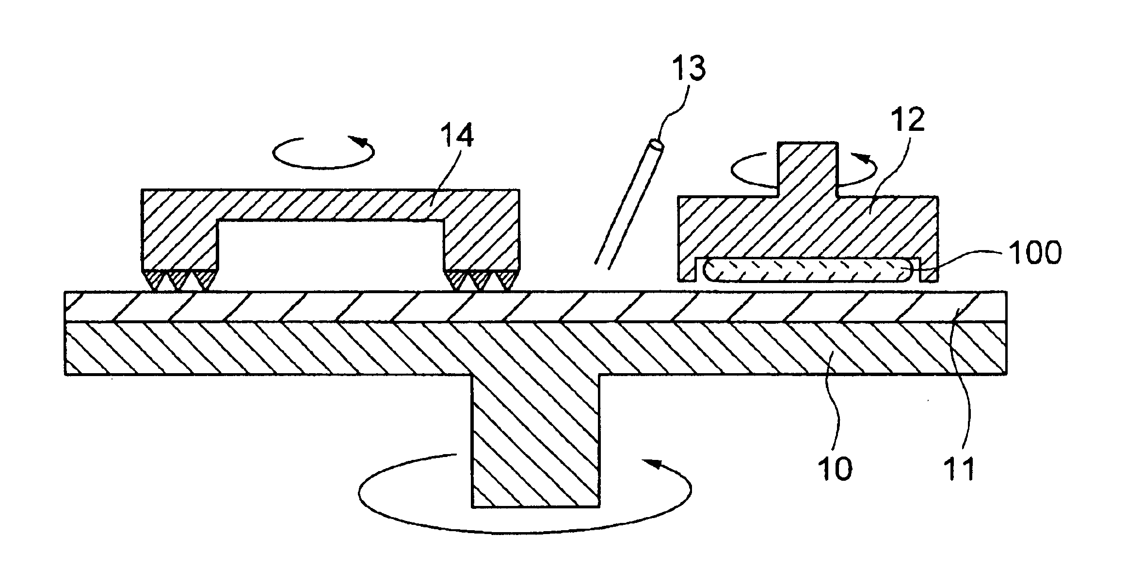
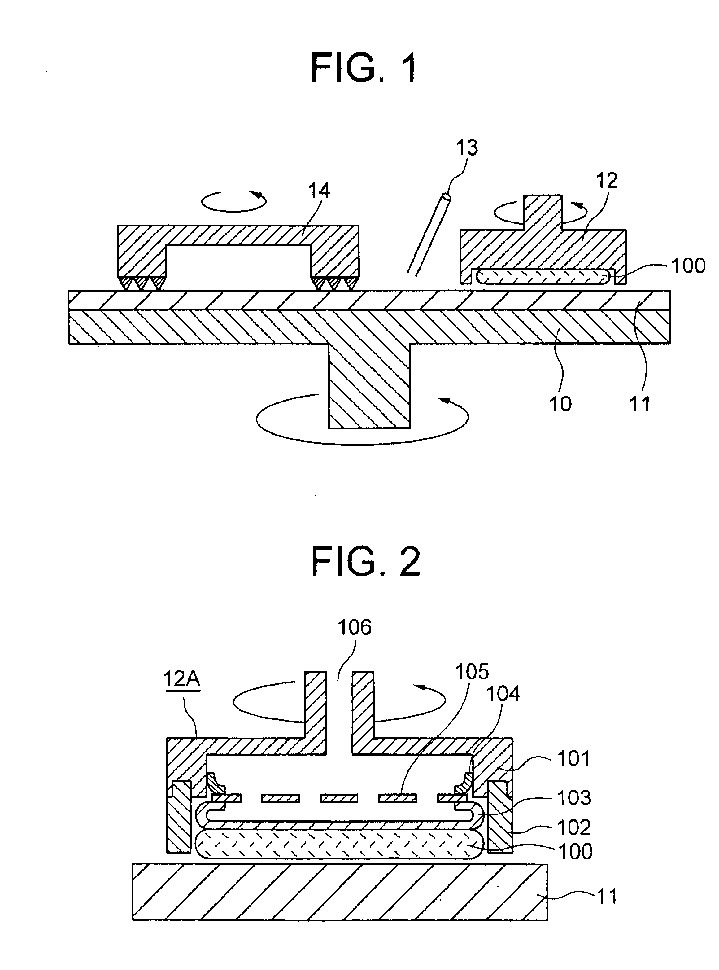
[0055]FIG. 1 shows a cross section of main portion of a polishing apparatus used in the present invention. A polishing pad 11 is adhered onto main surface of a rotational polishing platen 10, and slurry (not shown) containing substantially no abrasive grain, is supplied by a supply inlet 13. Size of the polishing pad 10 is eighteen inch in diameter in examples described below as long as there is not any notification. A wafer 100 consisting of four-inch-diameter silicon wafer, on surface of which one-micron-thickness Cu film (not shown) is formed, is pressed onto the polishing pad 11, with the wafer covered with a cover body covering the wafer or by a holder body (a carrier) 12 holding the wafer. A dresser 14 to process surface of the polishing pad (so-called “dressing”), is mounted on another main portion of the polishing platen 10, and textures the surface of the polishing pad by rotating it with pressing.

[0056]A foamed polyurethane resin pad, IC1000 (trade mark of RODEL) was used ...

example 2

[0069]Polishing was performed in same condition as the example 1, except that a retainer shown in FIG. 6 or FIG. 7 was used.

[0070]Specifically, a retainer 202C of FIG. 6 is made from typical epoxide resin. In the retainer 202C, a plurality of grooves 203 with V-shape cross section of 10-500 micron depth are formed at least into inner wall that may contact with the membrane 103, substantially in parallel with surface (retainer polishing surface) of the retainer where retainer contacts with the polishing pad (hence laterally). It was founded that the depth variation of 10 to 500 micron was generated as follows. A retainer of resin is usually not accurate circle, and necessarily has a certain deformation. The retainer in this example was also deformed, thus depth of the deepest groove was 500 micron, and depth of the shallowest groove was 10 micron. Groove angle of the V-shaped groove 203 was about 90 degrees. The groove formation decreased surface area that can contacts with the membr...

example 3

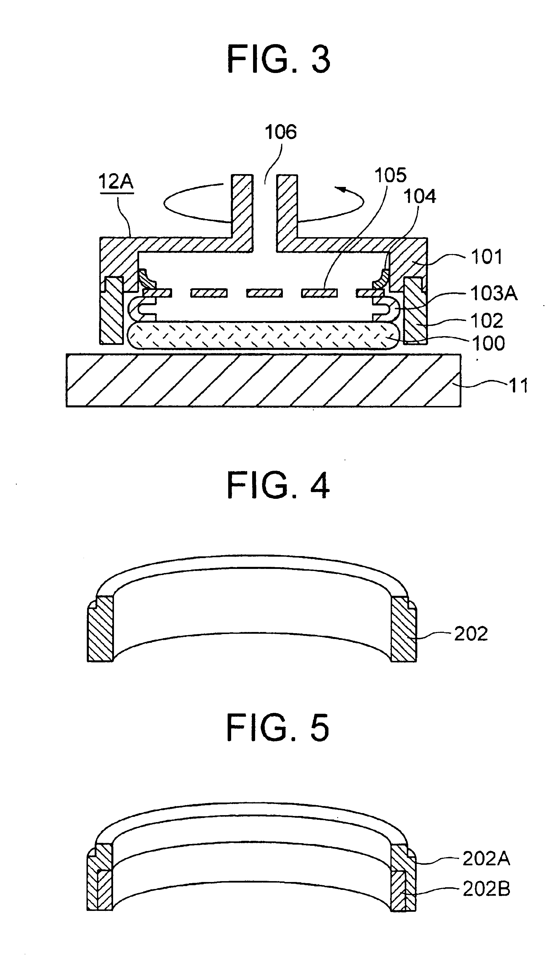
[0073]A wafer was polished in same condition as the example 1, except that a retainer in FIG. 8 was used. The retainer 202A, 202C is made of material of typical epoxide resin. In the retainer, ring 202a made of tetrafluoro resin with low coefficient of friction is embedded into inner wall of a part that may contact with the membrane, and a plurality of grooves 203A with V-shaped cross section and about 100 micron depth is formed substantially in parallel with the polishing surface, hence laterally. Groove angle of the V-shaped groove 203A was about 90 degrees. Use of resin with low coefficient of friction as well as formation of the grooves allowed surface area that may contact with the membrane to decrease to half of the initial one.

[0074]A carrier with a retainer as shown in FIG. 8 is employed in a polishing apparatus, then a sample of wafer similar to one in the example 1 (an interconnect substrate) was polished. As a result, stable polishing was provided during copper polishing,...


PUM

PropertyMeasurementUnit
Forceaaaaaaaaaa

Abstract

In a polishing apparatus having a cover body with fluid pressing mechanism, during polishing, vibration and migration of sticking portion between a retainer and a membrane generated in downstream of rotation of a polishing platen is prevented by reducing sticking force between the retainer and the membrane to less than force needed to wafer polishing with rotation of the cover body.

Description

CROSS REFERENCE TO RELATED APPLICATION[0001]This application is a continuation application of U.S. Ser. No. 09 / 811,496, filed Mar. 20, 2001 now U.S. Pat. No. 6,719,618, the contents of which are incorporated herein by reference.FIELD OF THE INVENTION[0002]The present invention relates to a polishing apparatus, which, in particular, is suitable for planarization of surfaces of work pieces such as semiconductor wafers for semiconductor integrated circuit devices with a multilayer interconnection comprising a plurality of metal films.BACKGROUND OF THE INVENTION[0003]Recently, it is seen that planarization of surfaces of interconnect substrates for large scale semiconductor integrated circuits (referred to as “LSI”s hereafter) is important. One of representative techniques for the planalization is the Chemical Mechanical Polishing; CMP (referred to as “polishing” as long as there is not any notification).[0004]The polishing techniques are classified roughly into two processes:[0005]a pr...

Claims


Application Information

Patent Timeline
IPC IPC(8): B24B37/04B24B37/005B24B37/30B24B37/32H01L21/304
CPCB24B37/30H01L21/304
Inventor HOMMA, YOSHIOKONDO, SEIICHISAKUMA, NORIYUKIYAMADA, YOUHEIKIMURA, TAKESHINEZU, HIROKI
Owner RENESAS TECH CORP
Why Eureka
Try Eureka