In situ catalyst regeneration/activation process

a catalyst and in situ technology, applied in the field of in situ catalyst regeneration/activation process, can solve the problems of high pyrophoric content of catalysts, and the inability to correct long-term catalyst deactivation

Inactive Publication Date: 2005-05-31
EXXON RES & ENG CO
View PDF9 Cites 11 Cited by
  • Summary
  • Abstract
  • Description
  • Claims
  • Application Information

AI Technical Summary

Benefits of technology

[0016]The invention provides for the continuous or semi-continuous, in situ regeneration of HCS catalysts. The method comprises periodic or continuous removal of catalyst from an operating HCS reactor to a regeneration vessel. In the regeneration vessel, the catalyst is then exposed to a regenerative environment such as a high temperature (300-500° C.) oxidative treatment. Finally, the catalyst is returned to the operating HCS reactor also containing catalyst rejuvenation means allowing reduction to occur at HCS process temperatures which completes the catalyst regeneration.

Problems solved by technology

However, once activated, the catalysts are usually highly pyrophoric.
Long-term catalyst deactivation is not corrected by rejuvenation.

Method used


Image

  • In situ catalyst regeneration/activation process
  • In situ catalyst regeneration/activation process
  • In situ catalyst regeneration/activation process

Examples


example 1

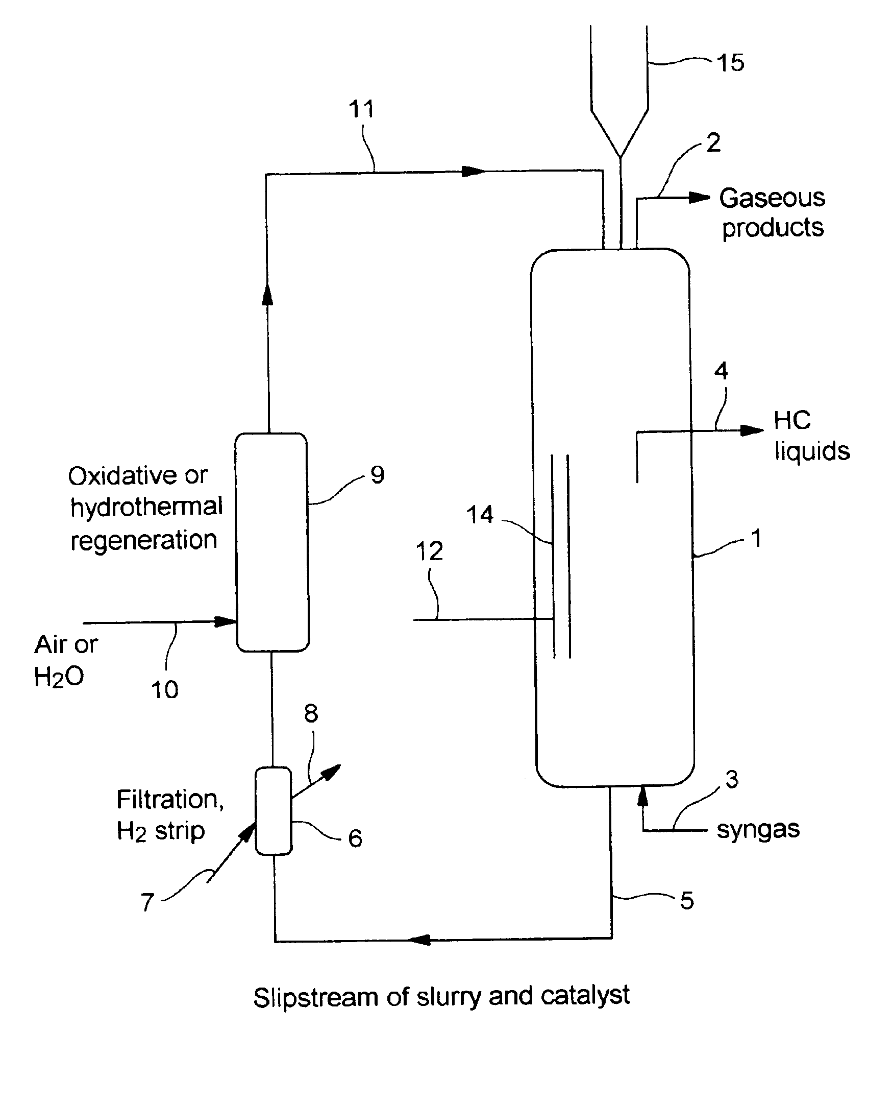
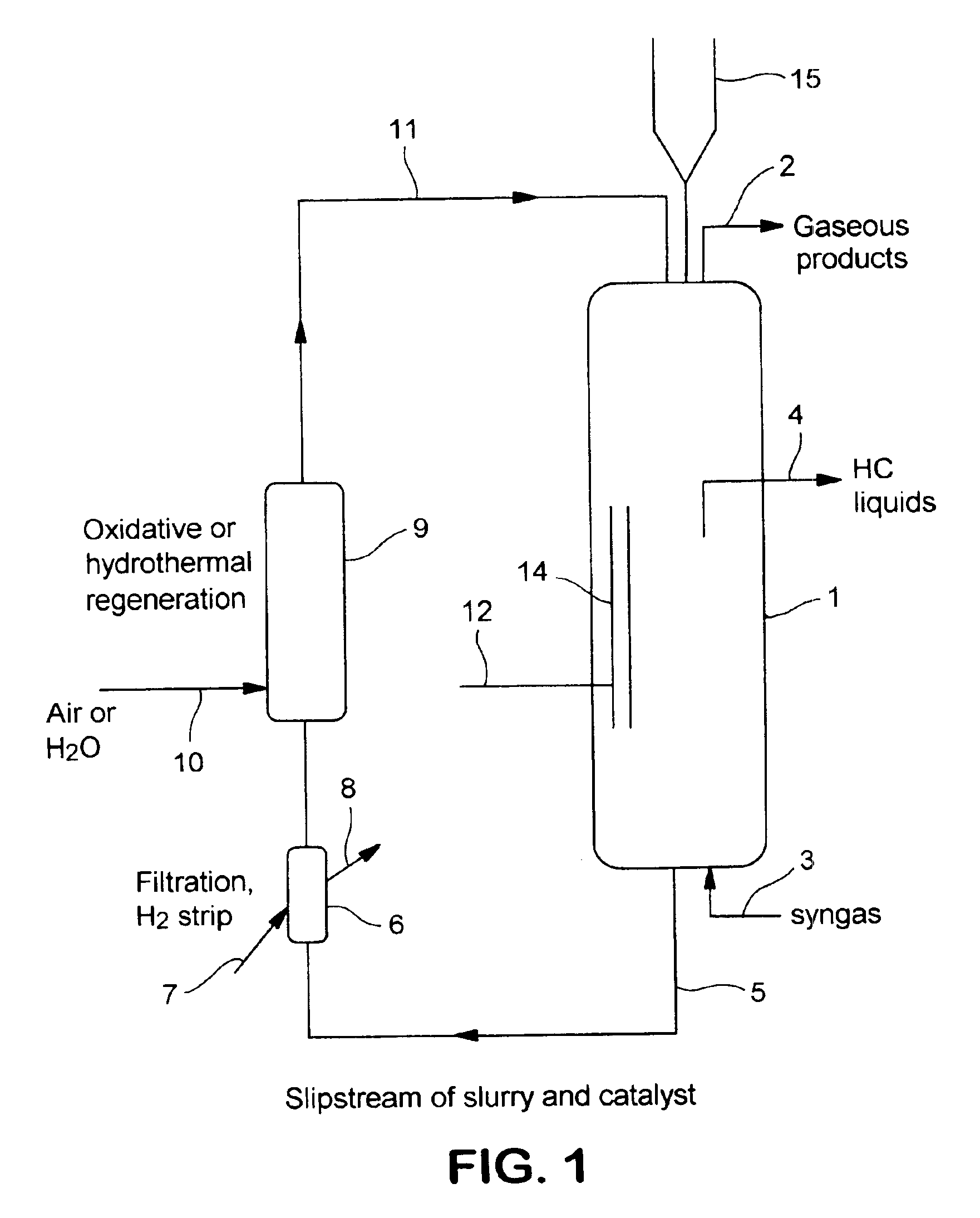
[0038]“Fresh” Co—Re catalyst on a TiO2 support was activated and placed in a Fischer-Tropsch reactor. Two samples were removed: an early-run sample, which was removed a few days after the reactor was in operation, and a late-run sample which was removed very late in the run cycle. Each sample was removed to a dry box and the wax extracted with hot toluene under inert conditions.

[0039]Each sample was divided into two portions. The first portion of each sample was directly transferred under inert condition into a chemisorption unit and the H2 chemisorptions, a standard measure of catalytic activity, were measured by a dual isotherm technique. This technique is described by C. H. Bartholomew in “H2 Adsorption on Supported Noble Metals and its Use in Determining Metal Dispersion”, Catalysis, Vol. 11, pp. 93-126 (1994) CODEN: CATADK ISSN: 0140-0568, CAN 123:66509 AN 1995:536025 CAPLUS. The second portion of each sample was regenerated in a high temperature (350° C.) oxidative (air) envir...

example 2

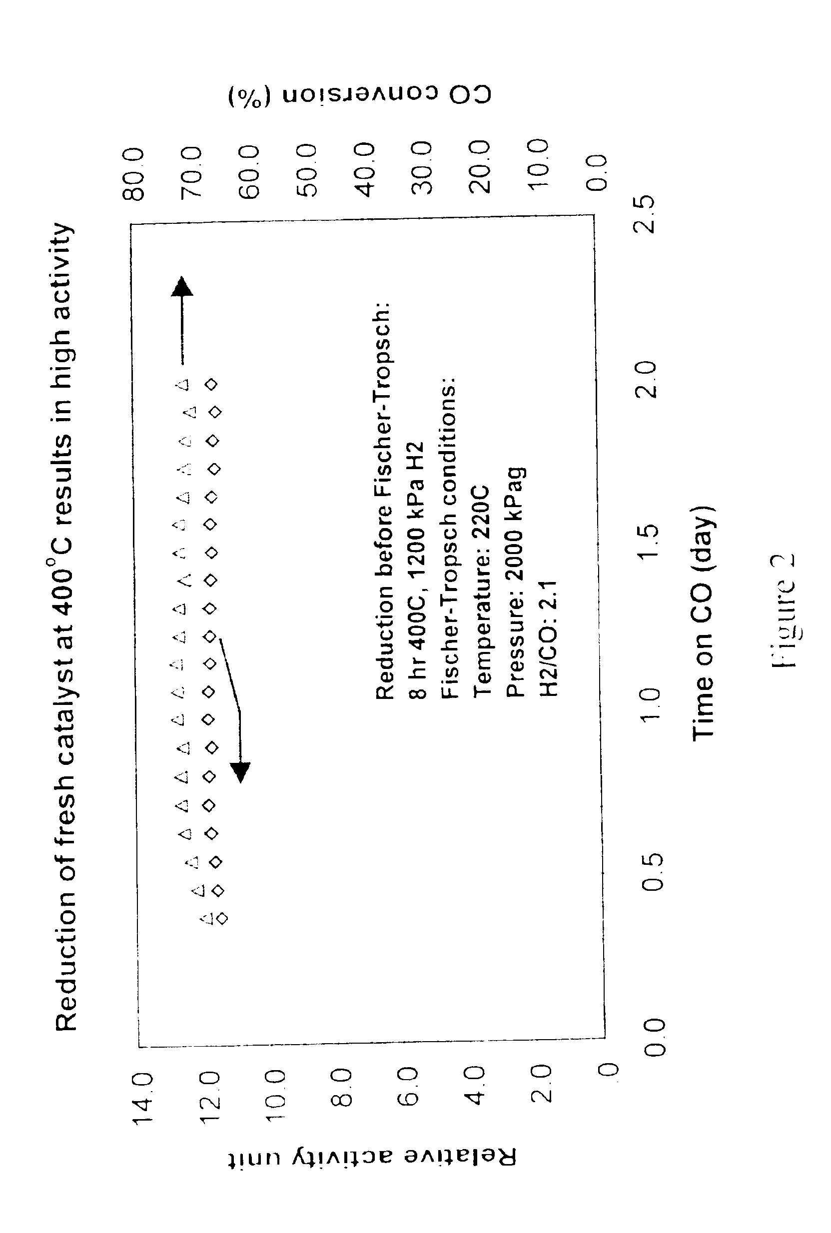
[0043]A “fresh” (non-activated) catalyst was reduced (activated) in a hydrogen atmosphere at high temperature conditions (1200 kPa, 400° C. for 8 hours). The catalyst was then placed in a Fischer-Tropsch synthesis reactor operated at 200° C., 20.25 bar with a 2.1 H2 / CO ratio. The activity of the catalyst was determined by measuring the catalyst productivity (moles of CO converted / volume of catalyst), adjusted for differences in reaction conditions using a kinetic model similar to those found in W. D. Deckwer, “Kinetic Studies of Fischer-Tropsch Synthesis on Suspended Fe / K Catalyst—Rate Inhibition by CO2 and H2O.”, Ind. Eng. Chem. Process Dev., Vol 25, pp. 643-649 (1986). Relative activity levels for this catalyst are reported in FIG. 2. The activity level for this “fresh”, high-temperature reduced catalyst averaged slightly less than 12.0 as expected.

example 3

[0044]The same experiment as in Example 2 was conducted except that the initial hydrogen reduction of the “fresh” catalyst was conducted at low-temperature rejuvenation conditions (220° C., 2000 kPa for 12 hours). As in example two, the catalyst was placed in a Fischer-Tropsch reactor (at the same operating conditions) and the relative activity was measured. The relative activities for this catalyst are reported in FIG. 3. The relative activity for this catalyst ranged between 5.0 and 5.5. These results clearly demonstrate that a low-temperature reduction of a “fresh” catalyst did not activate the catalyst to acceptable HCS activity levels.


PUM

PropertyMeasurementUnit
temperatureaaaaaaaaaa
mole ratioaaaaaaaaaa
pressureaaaaaaaaaa

Abstract

An in situ process for conducting regeneration of spent hydrocarbon synthesis catalyst. Regenerated, but not yet re-activated, catalyst (15) may be introduced into an operating HCS reactor (1) that has catalyst rejuvenation means (14). Any combination of a fresh, activated catalyst, a fresh, passivated catalyst or short-term or long-term deactivated catalysts may already be present in the HCS reactor (1). The regenerated, but not yet re-activated catalyst is activated in the HCS reactor (1) with rejuvenation means (14) at normal process conditions. The HCS reactor (1) receives syngas through the inlet line (3) and releases liquid hydrocarbons through outlet line (4) and gaseous hydrocarbon and unreacted syngas through the offgas line (2). Catalyst is removed from the HCS reactor (1) through the slipstream line (5) and into a filtration unit (6) which is fed with a stripping fluid (7). The filtered catalyst proceeds to the regeneration unit (9) which is fed a regenerative fluid (10). The regenerated catalyst is returned to the HCS Reactor (1) through the catalyst return line (11) where it is reactivated.

Description

FIELD OF THE INVENTION[0001]The present invention relates to an in situ method of regenerating catalysts used in Hydrocarbon Synthesis Catalytic (HCS) processes. Specifically, the present invention provides a means and process for in situ catalyst regeneration in which no “on-site” catalyst activation vessel is required and in which the catalyst can be activated in a Fischer-Tropsch reactor. More specifically, the present invention provides a means and process for supported bi-metallic cobalt catalyst regeneration without interrupting the hydrocarbon synthesis continuous slurry process flow scheme and without the need for any additional catalyst activation vessels.BACKGROUND OF THE INVENTION[0002]The preparation of hydrocarbons from a mixture of hydrogen and carbon monoxide at elevated temperature and pressure in the presence of a catalyst is referred to in the literature as the Fischer-Tropsch hydrocarbon synthesis (HCS). Depending on the catalyst and conditions, the hydrocarbons m...

Claims


Application Information

Patent Timeline
Patent Type & Authority Patents(United States)
IPC IPC(8): B01J23/90B01J23/94B01J23/96B01J38/12B01J38/10B01J38/00C10G2/00B01J23/889B01J38/18
CPCB01J23/94B01J23/96B01J38/10C10G2/333C10G2/00C10G2/332B01J38/12
Inventor SOLED, STUART LEONBAUMGARTNER, JOSEPH ERNESTKISS, GABOR
Owner EXXON RES & ENG CO
Why Eureka
Try Eureka