Baseline compensating method and camera used in millimeter wave imaging

a technology of baseline compensation and millimeter wave, which is applied in the field of millimeter wave imaging, can solve the problems of degrading image quality, increasing the difficulty of detecting those energy differences, and reducing the quality of images, so as to reduce or eliminate scene-independent baseline signals and improve image quality

Inactive Publication Date: 2005-05-31
MILLIVISION TECH
View PDF24 Cites 21 Cited by
  • Summary
  • Abstract
  • Description
  • Claims
  • Application Information

AI Technical Summary

Benefits of technology

[0014]The present invention involves a new and improved method of reducing or eliminating scene-independent baseline signals in output value signals from radiometer channels or receiver channels into which radiant energy from a scene is scanned by a movable scanning element during millimeter wave imaging. The present invention recognizes a probable cause of these scene-independent baseline signals, and describes a technique for measuring the baseline signals to compensate the output value signals for the purpose of composing a better quality image.
[0015]It is believed that the scene-independent baseline signals result from a standing wave which is established between an antenna of the channel and the movable scanning element. Because the movable scanning element introduces changes in geometry of the optical path through which radiant energy from the scene is scanned into the channels, the characteristics of the standing wave vary in relation to the position of the movable scanning element. Recognizing the dependency on the position of the movable scanning element allows the influence of the baseline signal to be measured at each position of the movable scanning element, so that the value of the baseline signal may thereafter be subtracted from the output value signals obtained directly from the channels. The result of the subtraction is a baseline-compensated output signal which more faithfully and accurately represents the brightness temperatures of points within the scene. Consequently, the characteristics of the scene may be more accurately imaged with contrast. Alternatively, less difference in radiated energy from different points within the scene is effective in creating images.

Problems solved by technology

Because passive millimeter wave imaging relies on the inherent natural energy emanating from the objects and the background in the scene, and such inherent natural energy is generally less than the amount of energy resulting from actively illuminating the scene with added energy, it is typically more difficult to create an image passively.
Slight differences in the brightness temperature of the objects and the background increase the difficulty of detecting those energy differences with enough distinction to create images with good contrast and resolution relative to the background.
Inadequate contrast, resulting from an inability to detect relatively small differences in radiated energy from point to point within the scene, degrades the quality of the image.
Millimeter wave imaging is further complicated by the fact that millimeter wave energy constitutes only a very small band or part of the spectrum of energy emitted by a body.
Moreover, the typical millimeter wavelength frequency band used in millimeter wave imaging is even further restricted, for example, at 94±2 GHz.
Consequently, the limited bandwidth also reduces the amount of energy available to be detected for use in creating millimeter wavelength images.
Further complications arise from the noise-like origin of the millimeter wavelength energy which is detected to create the images.
The thermally induced quantum effects result in a significant variations in frequency distribution and intensity of the emitted energy, thereby causing the radiated energy to have random characteristics similar, to noise.
However, there is no underlying pure signal in passive millimeter wave imaging, due to the thermally induced and random quantum effects which create the emitted radiation.
Thus, distinguishing the desired information carried by a noise-like signal from spurious and derogating noise-like signals of similar characteristics is a significant challenge in millimeter wave imaging.
One disadvantage of using multiple radiometer channels or receiver channels to obtain the multiple samples to be added together is that each channel has its own individual and particular response characteristics.
When the slightly different samples from the multiple channels are combined to create each pixel, the intensity of the pixel does not faithfully represent the brightness temperature of the corresponding point in the scene.
Adding signals which are slightly different, even when those signals originate from a single point in the scene with a uniform brightness temperature, results in slight derogation in contrast of the image.
Moreover because of the scanning effect, the anomalous effects introduced by the individual and different characteristics of each channel are distributed among various different pixels in the image, thereby decreasing the contrast and the quality of the image.
The use of such choppers, and the necessity to quickly readjust each channel while still measuring radiation from the scene, greatly complicates the imaging process and the equipment necessary to perform the imaging.
While gain normalization has enhanced the quality of the image, gain normalization has not eliminated image anomalies arising because of the particular differences in offset and noise temperature characteristics of the channels.
Moreover, the typical type of gain normalization employed in the prior art has been discovered not to account adequately for all variations in gain among the different channels.

Method used


Image

  • Baseline compensating method and camera used in millimeter wave imaging
  • Baseline compensating method and camera used in millimeter wave imaging
  • Baseline compensating method and camera used in millimeter wave imaging

Examples


Embodiment Construction

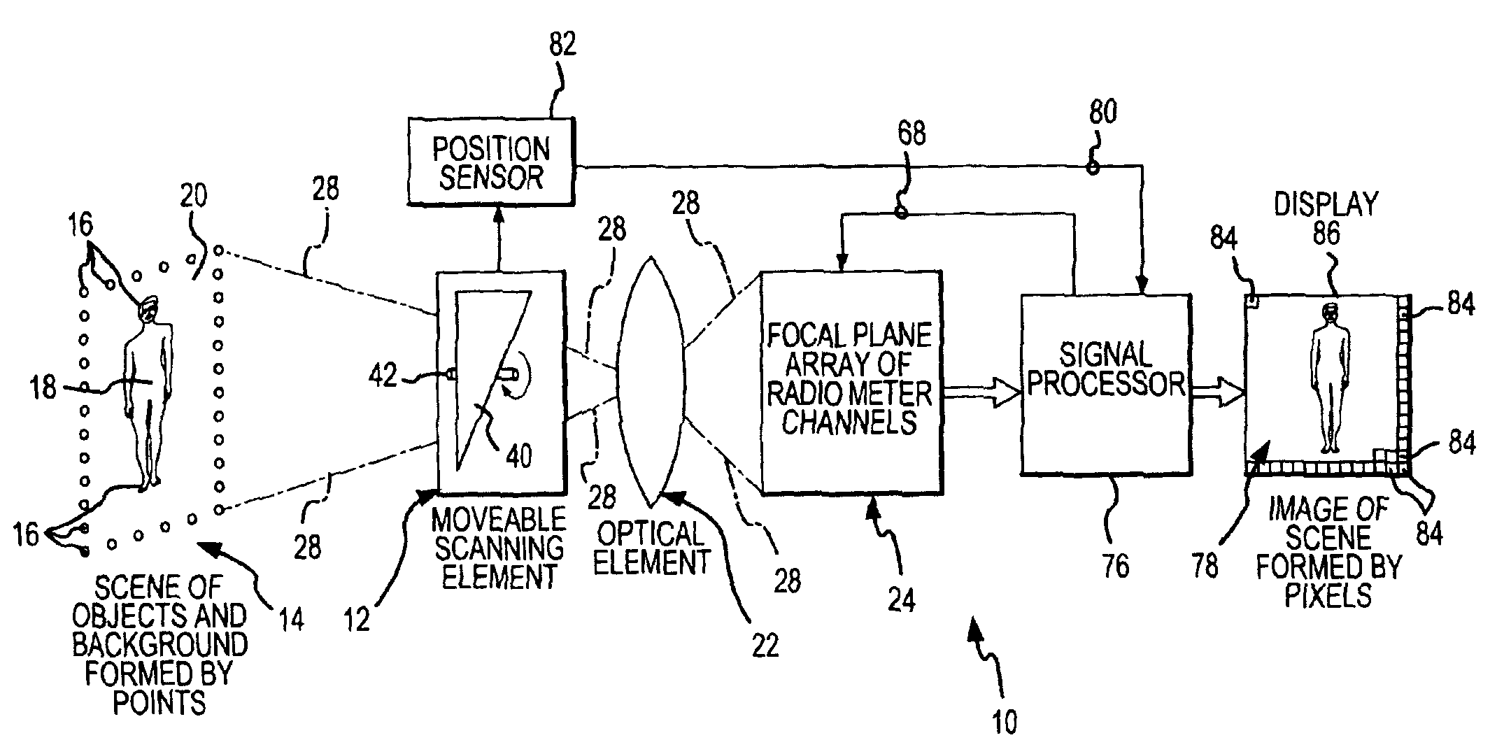
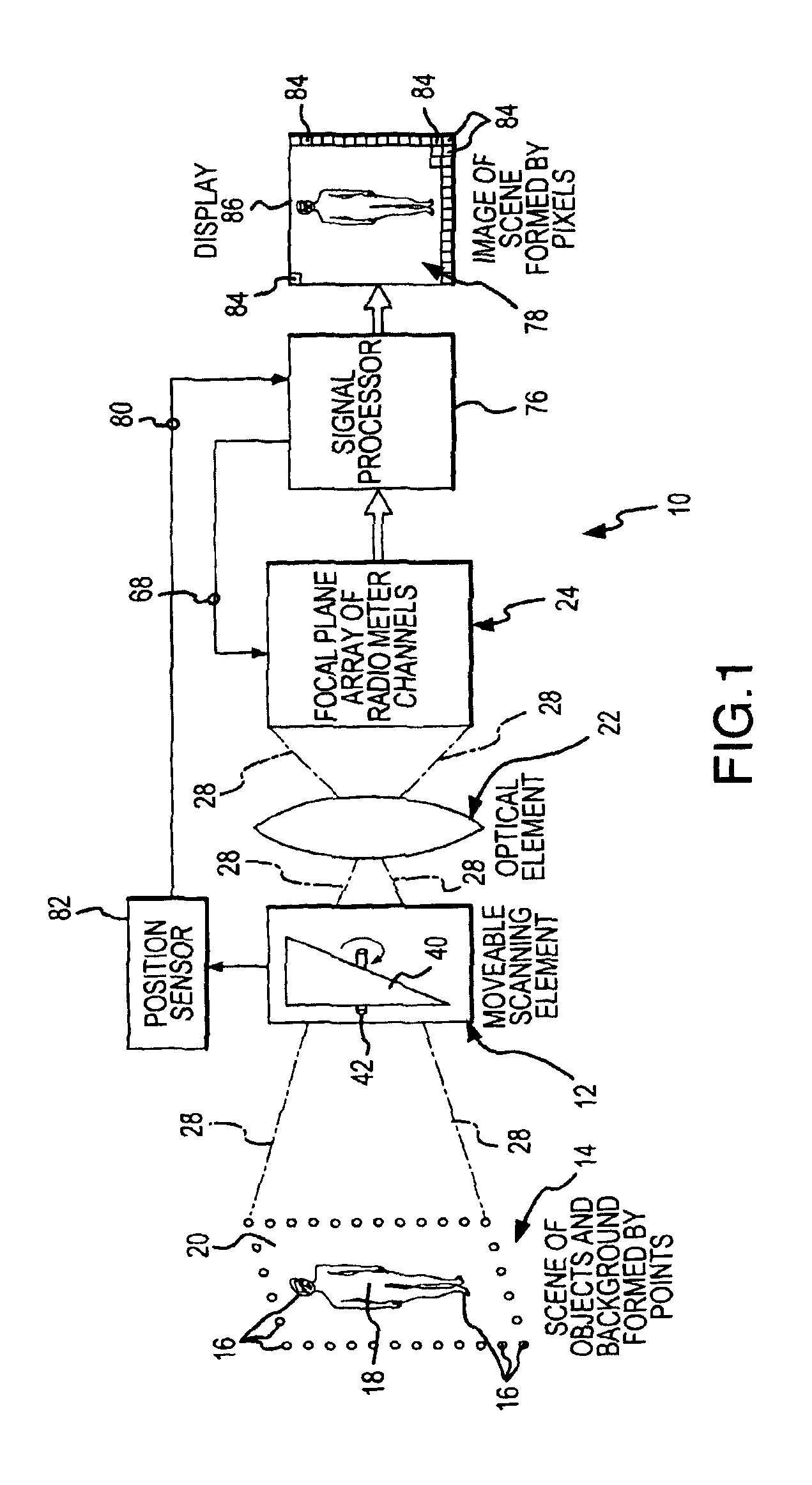
[0030]A camera 10, shown in FIG. 1, incorporates and operates in accordance with the various aspects of the present invention. The camera 10 includes a movable scanning element 12 which receives emitted and reflected radiation energy emanated from a scene 14. The scene 14 is formed by points 16, and each of the points 16 is either part of an object 18 within the scene 14 or part of a background 20 within the scene 14. The points 16 of the scene 14 emanate radiation energy with an intensity which is related to the brightness temperature of that point. The emanated radiation energy includes energy in a millimeter wavelength frequency band which is emitted and reflected from the objects 18 and the background 20.

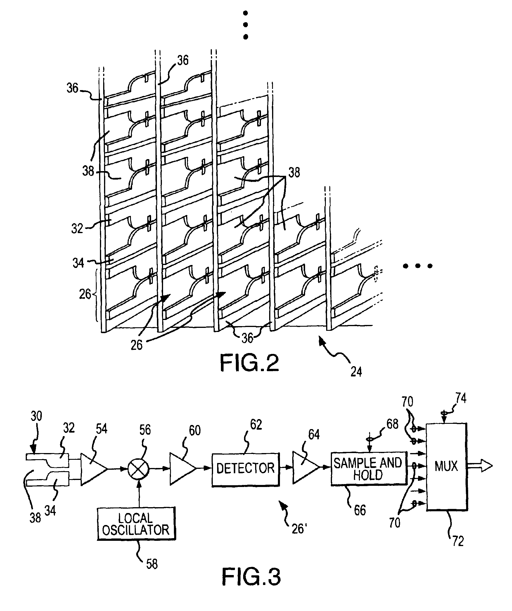
[0031]The movable scanning element 12 receives emanated energy from the scene 14, and directs or steers that energy through an optical element 22 to a focal plane array 24 of channels 26. Each channel 26 will typically be a radiometer channel when the camera 10 is used in passiv...


PUM


Abstract

Scene-independent baseline signals in output value signals from radiometer or receiver channels used in millimeter wave imaging are eliminated or reduced and an improved image is composed. The scene-independent baseline signals are believed to result from a standing wave which is established between an antenna of the channel and a movable scanning element which scans radiant energy from the scene into each channel. The movable scanning element introduces changes in geometry which change the characteristics of the baseline signals depending upon the position of the movable scanning element. The baseline signals are measured by viewing a scene of uniform brightness temperature, and the baseline signal contribution is subtracted from the output value signals from each channel. The baseline compensated output signals are used to compose an image with better contrast.

Description

CROSS-REFERENCE TO RELATED APPLICATION[0001]This application is related to U.S. patent applications for an invention for an Offset Drift Compensating Flat Fielding Method and Camera Used in Millimeter Wave Imaging Ser. No. (246.301), and for a Weighted Noise Compensating Method and Camera Used in Millimeter Wave Imaging, Ser. No. (246.303), both filed concurrently herewith and assigned to the assignee of the present application. The subject matter of these related applications are incorporated herein by this reference.FIELD OF THE INVENTION[0002]This invention generally relates to millimeter wave imaging. Millimeter wave imaging involves creating an image of a scene from millimeter wavelength energy signals emanating from the scene. More particularly, the present invention relates to a new and improved method and camera which compensates for a baseline signal anomaly associated with each of a plurality of radiometer channels or receiver channels which receive and detect millimeter w...

Claims


Application Information

Patent Timeline
Patent Type & Authority Patents(United States)
IPC IPC(8): G01J5/52H01Q13/08
CPCG01J5/52H01Q13/085G01S13/887
Inventor VAIDYA, NITIN M.HUGUENIN, G. RICHARD
Owner MILLIVISION TECH
Why Eureka
Try Eureka