Shared-current electronic systems

a technology of electronic systems and shared current, applied in the direction of amplifiers, amplifiers with semiconductor devices/discharge tubes, amplifiers, etc., can solve the problems of affecting the operation the maximum operating voltage of solid-state electronic devices is too low for the dc source voltage available, and the use of gallium arsenide fets has presented a problem, so as to achieve maximum isolation, prevent rf crosstalk, and maximize power efficiency

Inactive Publication Date: 2005-05-31
EMHISER RES
View PDF4 Cites 15 Cited by
  • Summary
  • Abstract
  • Description
  • Claims
  • Application Information

AI Technical Summary

Benefits of technology

[0043]For maximum power efficiency, rf chokes must be chosen to prevent coupling of the rf signal onto the dc power lines and to obtain maximum isolation between the series FETs, and thereby to prevent rf crosstalk.
[0044]Conventionally, rf power amplifying J-FETs are biased with a negative dc voltage applied to the gate terminal, a positive power supply dc voltage applied to the drain terminal, and the source terminal attached to a circuit ground. Preferably, however, as shown and taught herein, the source terminal of the lower FET is connected to an electrical ground through a resistor, thereby causing the FET to self-bias, eliminating the need for a negative voltage for the gate terminal.
[0045]As taught herein, selectively-chose

Problems solved by technology

Frequently, maximum operating voltages of solid-state electronic devices are too low for the dc source voltage that is available.
However, a major disadvantage of GaAsFETs is that the maximum operating voltage is commonly +10.0 volts dc.
Since gallium arsenide FETs have an operative voltage of +10.0 volts dc, the use of gallium arsenide FETs has presented a problem.
This type of regulation has the disadvantages of excessive heat generation and low power efficiency.
This type of regulation has the advantage of low heat dissipation and high power efficiency, but has the disadvantages of increased cost; space inefficiency, due to large size; and the creation of a spurious signal on the rf carrier (EMI problems) due to the switching action of the regulator.
At higher rf powers, problems associated with inadequate rf decoupling have included low power efficiency, oscillation, a decrease in reliability of the circuits, and destruction of the solid-state devices.
The problem of rf decoupling intensifies for rf amplifiers that operate over a wide band of frequencies.
While one reason for connecting solid-state devices includes the low operating voltages of GaAsFETs, some dc source voltages are too high for other types of solid-state devices.
For instance, some telephone systems operate at 50.0 volts, which is too high for many solid-state electronic devices, such as some bipolar-jun

Method used


Image

  • Shared-current electronic systems
  • Shared-current electronic systems
  • Shared-current electronic systems

Examples


Embodiment Construction

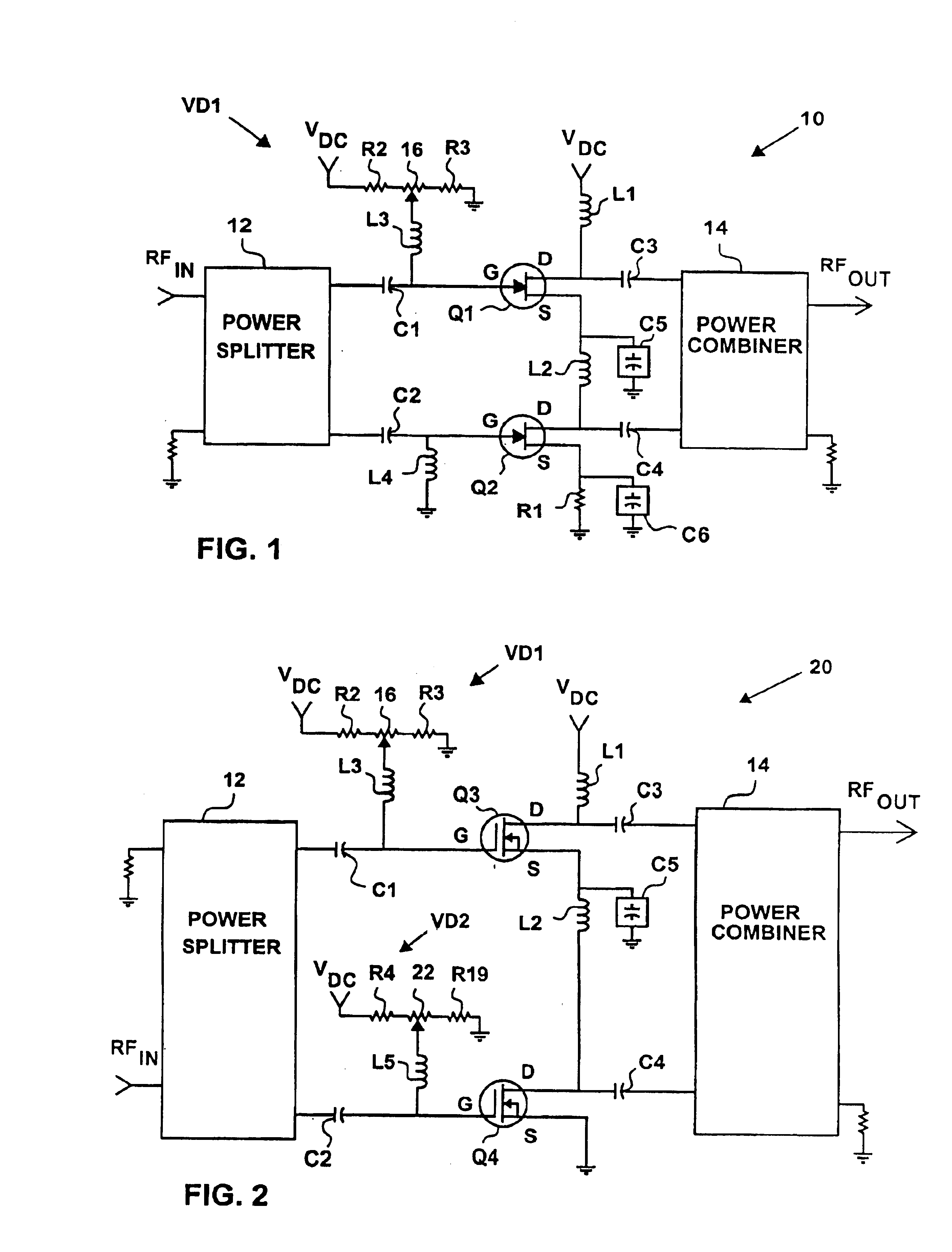
[0075]Referring now to FIG. 1, an rf power amplifier, or shared-current electronic system, 10 includes solid-state amplifying devices, solid-state electronic devices, n-channel gallium arsenide field-effect transistors, GaAsFETs, or FETs, Q1 and Q2 that are connected in series between a positive supply voltage, or source voltage, VDC and an electrical ground.

[0076]A first rf choke L1 connects the supply voltage VDC to a drain terminal of the FET Q1, a second rf choke L2 connects a source terminal of the FET Q1 to a drain terminal of the FET Q2, and a resistor R1 connects a source terminal of the FET Q2 to the electrical ground.

[0077]The rf power amplifier 10 also includes an rf power splitter 12 and an rf power combiner 14. The rf power splitter 12 is connected to gate terminals of the FETs Q1 and Q2, respectively, by coupling capacitors C1 and C2. The rf power combiner 14 is connected to drain terminals of the FETs Q1 and Q2, respectively, by coupling capacitors C3 and C4. And sour...


PUM


Abstract

Shared-current electronic systems (10, 20, 26, 30, 38, 48, 66, 70, 82, 90, 96, 100, 104, 108, 118, and 122) include two or more solid-state electronic devices, such as a solid-state amplifying device Q1, a baseband processor 110, and a multiplier/upconverter 112, that are connected in dc series or dc series-parallel, and that either fixedly or variably share percentages of a dc supply voltage. Various embodiments produce separate rf outputs, variably shift the phase of a single rf output, variably shift rf power between/among rf outputs, or produce a frequency-compressed modulation. RF decoupling of the dc series-connected electronic devices comprises making an effective series resistance (ESR) of an rf decoupling capacitance lower than the ESR of a porcelain capacitor that resonates at the operating frequency of the electronic device that is being decoupled.

Description

CROSS-REFERENCES TO RELATED APPLICATIONS[0001]This patent application is a Continuation-in-Part of U.S. patent application Ser. No. 10 / 602,442, filed Jun. 24, 2003, which is a Continuation of U.S. patent application Ser. No. 10 / 028,844, filed Dec. 20, 2001, now U.S. Pat. No. 6,683,499, which claims priority to Provisional Patent Application No. 60 / 258,341, filed Dec. 27, 2000, and is also a Continuation-in-Part of U.S. patent application Ser. Nos. 10 / 177,572, filed Jun. 21, 2002, now U.S. Pat. No. 6,747,517, Ser. No. 10 / 091,056, filed Mar. 4, 2002, now U.S. Pat. No. 6,690,238, and Ser. No. 10 / 028,844, filed Dec. 20, 2001, now U.S. Pat. No. 6,683,499, which all claim priority to Provisional Patent Application No. 60 / 258,341, filed Dec. 27, 2000.STATEMENT RE FEDERALLY SPONSORED RESEARCH OR DEVELOPMENT[0002]Not ApplicableREFERENCE TO SEQUENCE LISTING[0003]Not ApplicableBACKGROUND OF THE INVENTION[0004]1. Field of the Invention[0005]The present invention relates generally to connecting ...

Claims


Application Information

Patent Timeline
IPC IPC(8): H03F3/60H03F1/30
CPCH03F3/601H03F1/301H03F1/0283
Inventor LAUTZENHISER, BARRY ARTHURLAUTZENHISER, LLOYD LYNN
Owner EMHISER RES
Why Eureka
Try Eureka