Method of adding a device to a network

a network and device technology, applied in the field of home automation, can solve the problems of too long delay in the proliferation of automation systems in the home, and achieve the effect of making the binding process much simpler

Inactive Publication Date: 2005-05-31
LEVITON MFG
View PDF11 Cites 506 Cited by
  • Summary
  • Abstract
  • Description
  • Claims
  • Application Information

AI Technical Summary

Benefits of technology

[0026]Alternatively, a hand held tool that operates over any type of wireless media such as IR or RF can be employed as well. The chief benefit of using a wireless media type is that devices installed in difficult to reach places can be bound in a simple manner. Alternatively, line of sight or IR binding can be employed in combination with an AutoCAD layout of the facility. This functions to bind the devices together in addition to having the binding information automatically saved in an AutoCAD file which identifies the physical location of the device within the building. This functionality may be useful for certain fire and safety code requirements for certain systems.
[0027]Further, software icons can be created and placed on a touch screen equipped computer thus making the binding process much simpler such as during the initial installation so as to verify that the devices were wired and installed correctly. The detailed binding of some devices may be performed initially or may be performed after installation by a more highly trained individual. In accordance with the invention, the results of the simple binding method are readable, importable to another device and are able to be used by higher end network management tools (if any are present).
[0030]The invention comprises means of providing a consistent user interface for the device and consistent feedback from the device. For simple devices, for example, a momentary pushbutton may is employed on the devices and the feedback to the user comprises an LED. This may be used in low cost implementations of the invention.

Problems solved by technology

One of the major technological issues, however, that have hindered the proliferation of automation systems (such as LonWorks and others) in the home, is that users feel (1) it takes too long, (2) that it always requires a computer and (3) that it is too complicated a process to install and setup a device.
In particular, the part of the installation or configuration process that is most problematic is the binding portion, where electrical devices are configured to be recognized by other entities on the network once they have been physically and electrically installed.
The complexity in setting up the system grows, as the complexity of the features installed in the home becomes more sophisticated.
Unfortunately, setting up a system using currently available devices is not as simple as choosing the desired devices and wiring them into the network.
Wiring the devices is relatively simple and straightforward; the task of ensuring that devices know whom they are, what they are supposed to do and how to talk to other devices on the network is difficult.
As the technical expertise of the installer increases, the cost to employ that installer increases, adding cost to the automation system.
The recommended method, however, is very slow, tedious and confusing to a user.
It also consumes considerable firmware overhead for each device.
Groups are not supported and user feedback is not uniform permitting the same indication to mean several different modes of operation.
LonWorks has the disadvantage of requiring an installation tool.
Such tools are relatively difficult to operate and are relatively expensive, placing them out of reach of the typical consumer.
It does not have any provisions for cross-linked groups and is generally a one-way system, providing for a limited number of devices with limited functionality.

Method used


Image

  • Method of adding a device to a network
  • Method of adding a device to a network
  • Method of adding a device to a network

Examples


Embodiment Construction

[0073]

Notation Used ThroughoutThe following notation is used throughout this document.TermDefinitionACAlternating CurrentBACNetBuilding Automation and Control NetworkCEBusConsumer Electronics BusDIYDo It YourselfDLLDynamic Link LibraryEEPROMElectrically Erasable Programmable Read Only MemoryHpnpHome Plug And PlayHVACHeating Ventilation Air ConditioningICIntegrated CircuitIRInfraredLANLocal Area NetworkLCDLiquid Crystal DisplayLEDLight Emitting DiodeOSOperating SystemPCPersonal ComputerPDAPersonal Digital AssistantRAMRandom Access MemoryRFRadio FrequencyROMRead Only MemorySNVTStandard Network Variable TypeUSBUniversal Serial BusVCRVideo Cassette RecorderWANWide Area Network

General Description

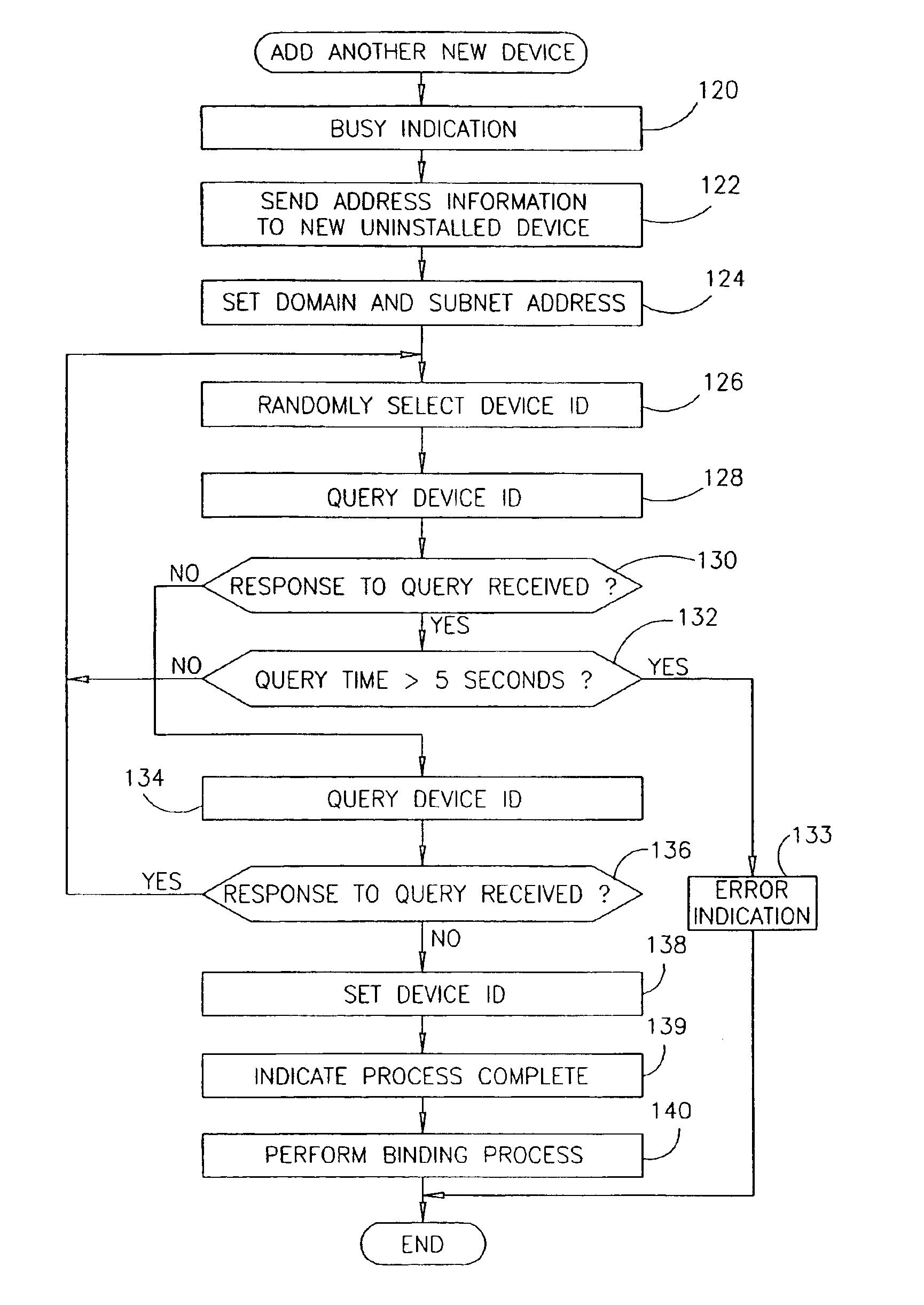
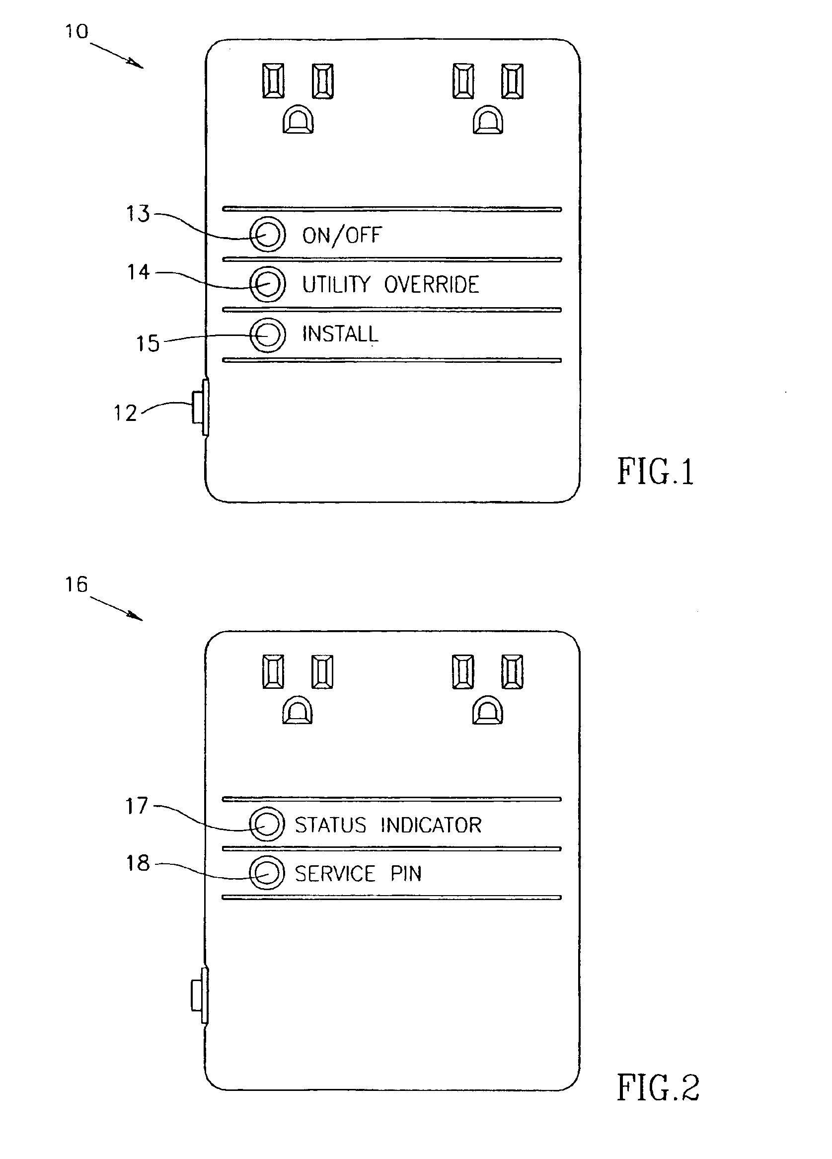
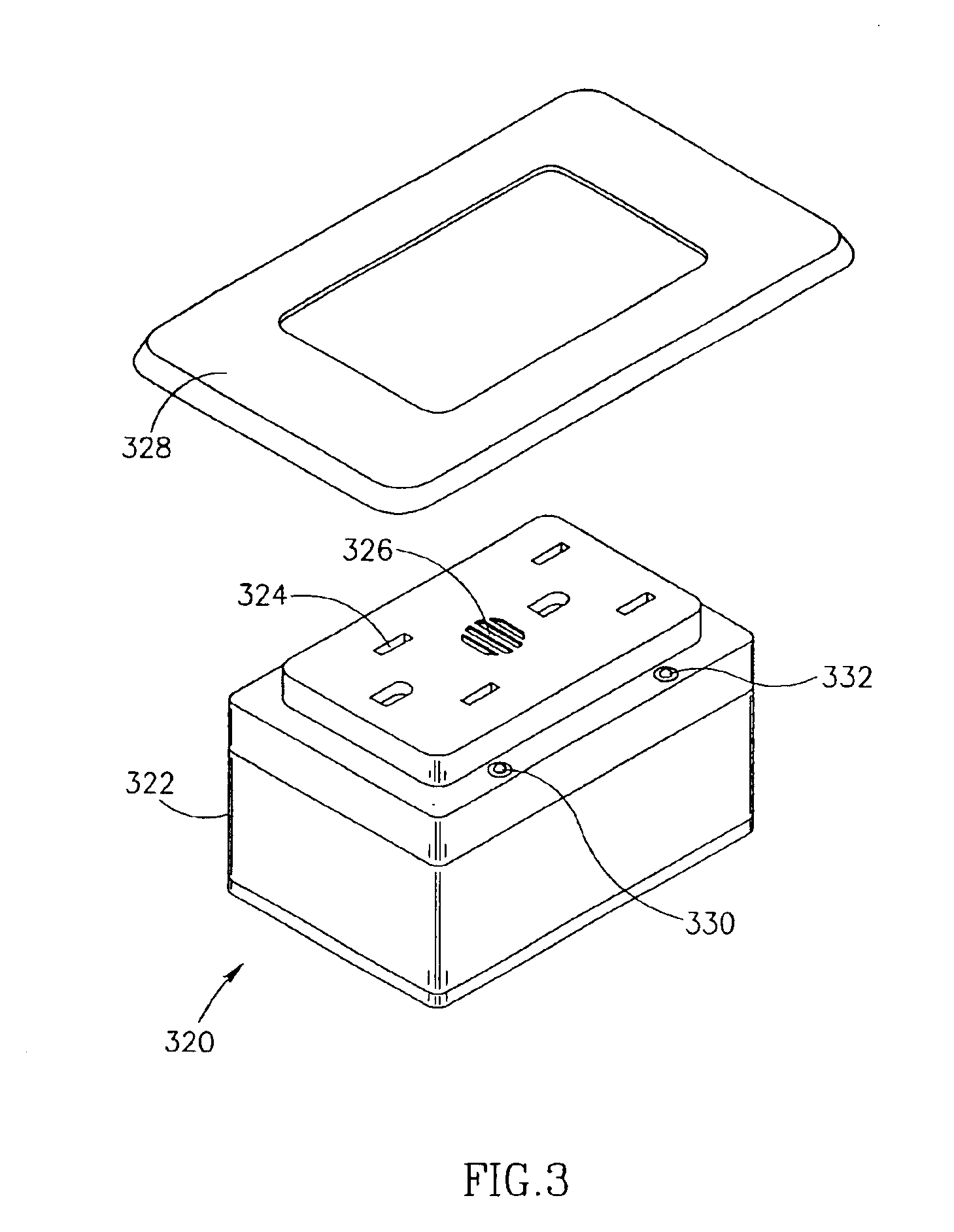
[0074]The present invention comprises a method of connecting electrical or electronic devices to an automation or multimedia network such that they are assigned an address and are configured so as to be recognized by other devices on the network. The automation network may be adapted for home, in...


PUM


Abstract

A method of adding a device to an existing or new electrical or electronic automation or multimedia network. The invention facilitates adding a device to the network that can communicate using various protocols such as LonWorks, CEBus, X-10, etc. over media such as AC power line, IR, RF, twisted pair, optical fiber, etc. The method is a mechanism for adding a device to a system that can be used by an ordinary user of network capable electrical devices. The method comprises the steps an installer would perform including the handshaking that needs to occur between devices to accomplish the binding process. A Functional Profile for LonWorks networks is given as an example. This includes a Home Device profile that employs an automated explicit type messaging for all devices intended for use in a home environment. The invention includes adding to the device an install button and a visual indicator for status such as an LED. Alternatively, existing buttons and LEDs on the device may be used for installed and binding purposes. Other methods of binding can be employed by the use of wired or wireless handheld tools, remote controls, etc. Other interfaces and user feedback can be used such as touch screen, personal computers, cellular phones, PDAs, etc which can offer simple ‘virtual’ binding by the press of an icon versus the physical button on the device. The binding can be performed locally or remotely such as via LAN, WAN, Internet, etc.

Description

REFERENCE TO RELATED APPLICATIONS[0001]This application claims the benefit of U.S. Provisional Application Ser. No. 60 / 116,832, filed Jan. 22, 1999, entitled “Apparatus For and Method of Binding A Device to a Network Interoperable,” incorporated herein by reference.FIELD OF THE INVENTION[0002]The present invention relates generally to the field of home automation and more particularly to a method of adding (e.g., binding) one or more devices to an electrical network such as the LonWorks automation network or a multimedia network.BACKGROUND OF THE INVENTION[0003]Today, automation systems are being installed in more and more buildings, including both new construction and in structures that are being rebuilt. The incentives for putting automation systems into a building are numerous. High on the list are reduced operating costs, more efficient use of energy, simplified control of building systems, ease of maintenance and of effecting changes to the systems. Facility managers would pref...

Claims


Application Information

Patent Timeline
Patent Type & Authority Patents(United States)
IPC IPC(8): G06F15/16G06F15/177G06F15/173
CPCH04L12/2809H05B37/0245H04L61/2092H04L29/1232H05B47/175H04L61/5092
Inventor BONASIA, GAETANOECKEL, DAVID P.HEBEISEN, STEPHEN P.MERNYK, ROSS
Owner LEVITON MFG
Why Eureka
Try Eureka