Prosthesis for the replacement of a posterior element of a vertebra

a technology for posterior elements and vertebrae, applied in the field of surgical devices and methods, can solve problems such as limiting the range of motion, reducing function, and causing debilitating pain

Inactive Publication Date: 2005-06-07
GLOBUS MEDICAL INC
View PDF63 Cites 310 Cited by
  • Summary
  • Abstract
  • Description
  • Claims
  • Application Information

AI Technical Summary

Benefits of technology

[0016]As a result, one object of the present invention is to provide a novel prosthesis for the replacement of all four of the facets so as to remove the source of traumatic, arthritic or other disease-mediated pain.

Problems solved by technology

Traumatic, inflammatory, metabolic, synovial, neoplastic and degenerative disorders of the spine can produce debilitating pain that can have severe socioeconomic and psychological effects.
For example, while spine fusion generally helps to eliminate certain types of pain, it has also been shown to decrease function by limiting the range of motion for patients in flexion, extension, rotation and lateral bending.
Furthermore, it is believed that spine fusion creates increased stresses on (and, therefore, accelerated degeneration of) adjacent non-fused motion segments.
Additionally, pseudoarthrosis, resulting from an incomplete or ineffective fusion, may reduce or even totally eliminate the desired pain relief for the patient.
Also, the fusion device(s) used to effect fusion, whether artificial or biological, may migrate out of the fusion site, thereby creating significant new problems for the patient.
However, the artificial discs developed to date do not adequately address the mechanics of motion of the spinal column.
However, the facet joints can also be a significant source of spinal disorders and, in many cases, debilitating pain.
There is currently a lack of good interventions for facet joint disorders.
Furthermore, problems with the facet joints can also complicate treatments associated with other portions of the spine.
Additionally, at least in the case of surface replacements for osteoarthritic femoral heads, the capping of articular bone ends has proven to lead to clinical failure by means of mechanical loosening.
This clinical failure is hypothesized to be a sequela of disrupting the periosteum and ligamentum teres femoris, both serving a nutrition delivery role to the femoral head, thereby leading to avascular necrosis of the bony support structure for the surface replacement.
It is possible that corresponding problems could develop from capping the facet.
Another potential disadvantage of facet capping is that in order to accommodate the wide variability in anatomical morphology of the facets, not only between individuals but also between levels within the spinal column, a very wide range of cap sizes and shapes is required.
Like the design of the aforementioned U.S. Pat. No. Re. 36,758, the prosthesis of U.S. Pat. No. 6,132,464 generally preserves existing bony structures and therefore does not address pathologies which affect the bone of the facets in addition to affecting the associated cartilage.
However, the lamina is a very complex and highly variable anatomical surface.
As a result, in practice, it is very difficult to design a prosthesis that provides reproducible positioning against the lamina so as to correctly locate the cartilage-replacing blades for the facet joints.
Thus it will be seen that previous attempts to provide facet joint replacement have proven inadequate.
In some circumstances, additional structures of a vertebra beside the facets may have been compromised by disease or trauma.

Method used


Image

  • Prosthesis for the replacement of a posterior element of a vertebra
  • Prosthesis for the replacement of a posterior element of a vertebra
  • Prosthesis for the replacement of a posterior element of a vertebra

Examples


Embodiment Construction

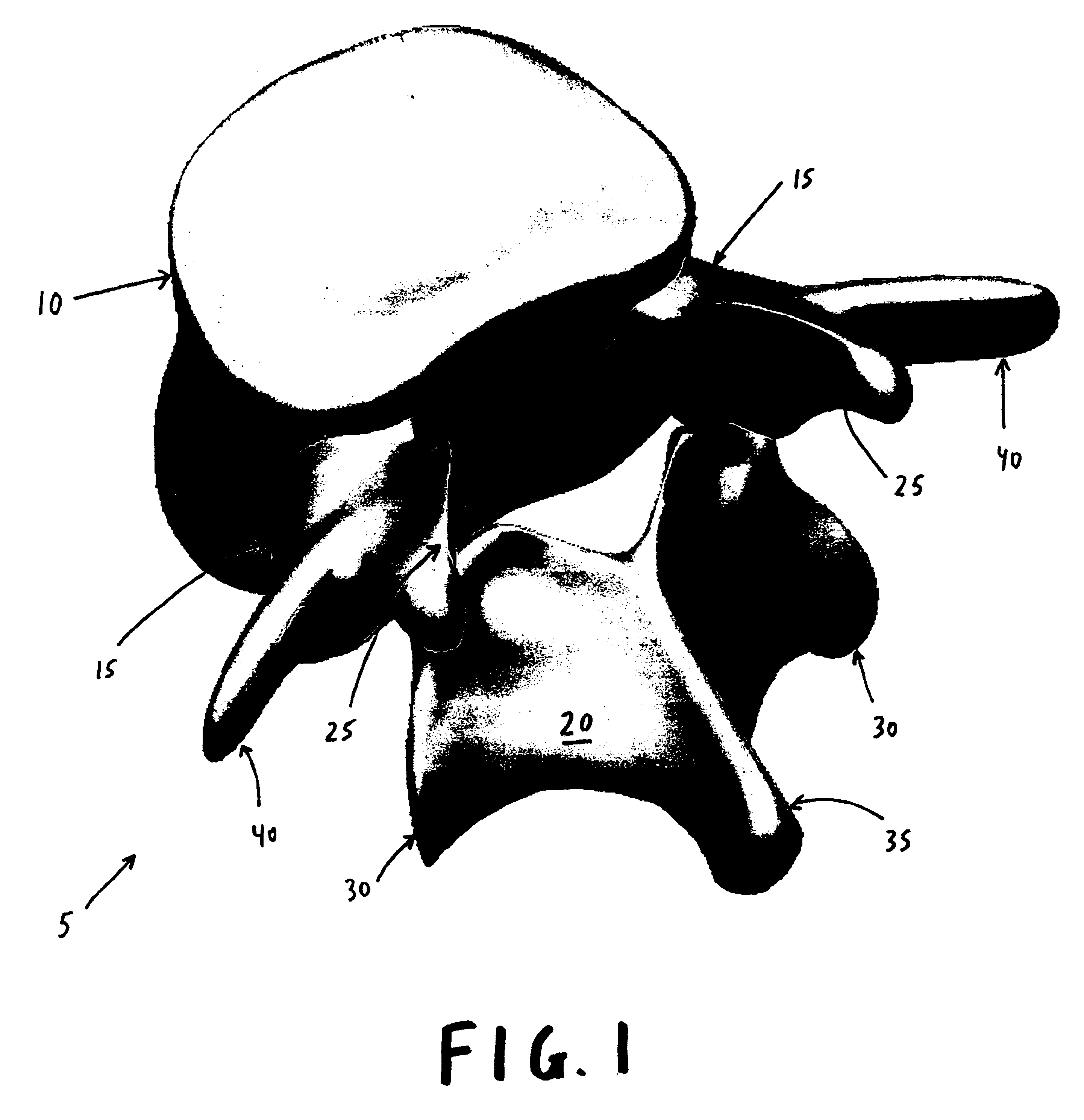
[0056]Referring now to FIG. 1, there is shown a natural lumbar vertebra 5 comprising a natural vertebral body 10, a pair of natural pedicles 15 extending from natural vertebral body 10, a natural lamina 20 extending from natural pedicles 15, a pair of natural superior facets 25 extending from natural pedicles 15 and natural lamina 20, a pair of natural inferior facets 30 extending from natural lamina 20, a natural spinous process 35 extending from natural lamina 20, and a pair of natural transverse processes 40 extending from natural pedicles 15.

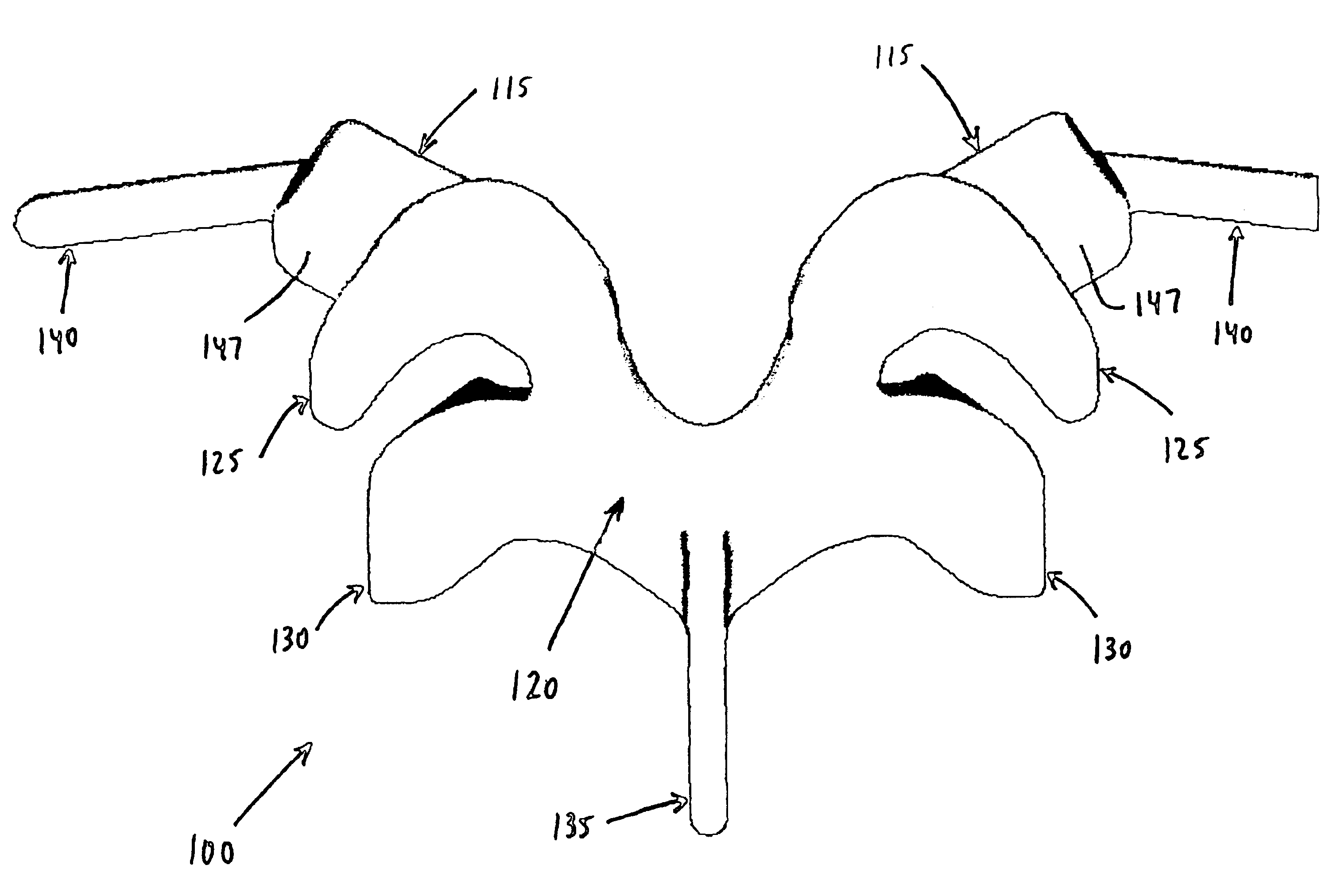
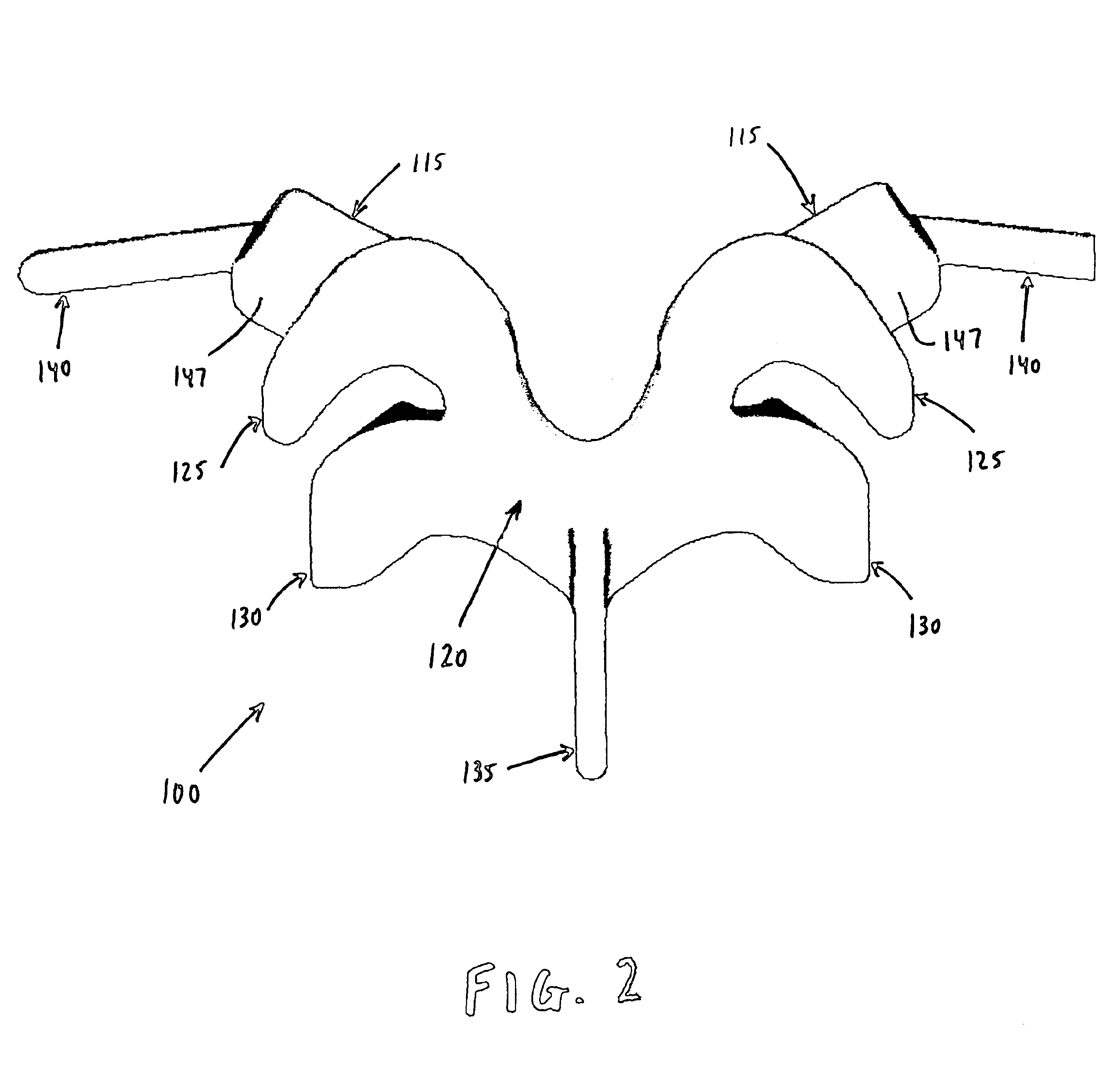
[0057]Looking next at FIGS. 2 and 3, there is shown a novel prosthesis 100 which is adapted to replace the natural lamina 20, the two natural superior facets 25, the two natural inferior facets 30, the natural spinous process 35, and the two natural transverse processes 40. To this end, prosthesis 100 comprises a pair of prosthetic mounts 115, a prosthetic lamina 120 extending from prosthetic mounts 115, a pair of prosthetic superior facets ...


PUM


Abstract

A prosthetic replacement for a posterior element of a vertebra comprising portions that replace the natural lamina and the four natural facets. The prosthetic replacement may also include portions that replace one or more of the natural spinous process and the two natural transverse processes. If desired, the prosthesis replacement may also replace the natural pedicles. A method for replacing a posterior element of a vertebra is also provided.

Description

[0001]This is a continuation of U.S. patent application Ser. No. 09 / 797,309, filed Mar. 1, 2001 now U.S. Pat. No. 6,419,703 by T. Wade Fallin et al. for PROSTHESIS FOR THE REPLACEMENT OF A POSTERIOR ELEMENT OF A VERTEBRA.BACKGROUND OF THE INVENTION[0002]1. Field of the Invention[0003]The present invention relates to surgical devices and methods in general, and more particularly to surgical devices and methods for restoring a damaged, diseased or otherwise painful spinal joint.[0004]2. Description of Related Art[0005]Traumatic, inflammatory, metabolic, synovial, neoplastic and degenerative disorders of the spine can produce debilitating pain that can have severe socioeconomic and psychological effects.[0006]One of the most common surgical interventions today is arthrodesis, or spine fusion, in which two or more adjacent vertebral bodies are fused together in order to alleviate pain associated with the disc(s) located between those vertebral bodies. Approximately 300,000 such procedur...

Claims


Application Information

Patent Timeline
Patent Type & Authority Patents(United States)
IPC IPC(8): A61F2/44A61F2/30
CPCA61F2/4405A61F2002/30604A61F2002/30578A61B17/86A61B2560/0443
Inventor FALLIN, T. WADEGOBLE, E. MARLOWEHOY, ROBERT W.
Owner GLOBUS MEDICAL INC
Why Eureka
Try Eureka