
Apparatus for sensing volatile organic chemicals in fluids

a technology of volatile organic chemicals and apparatus, applied in calibration apparatus, instruments, specific gravity measurement, etc., can solve the problems of time-consuming and relatively expensive process, and achieve the effect of simplifying background correction for the response of the chemiresistor, improving sensitivity and selectivity for sensing vocs

Inactive Publication Date: 2005-06-07
NAT TECH & ENG SOLUTIONS OF SANDIA LLC
View PDF15 Cites 96 Cited by
  • Summary
  • Abstract
  • Description
  • Claims
  • Application Information

AI Technical Summary

Benefits of technology

[0005]An advantage of the present invention is that an improved sensitivity and selectivity for sensing of VOCs is provided by the combination of the chemical preconcentrator and the chemiresistor(s) as compared to the use of chemiresistors alone.
[0006]Another advantage is that background correction for the response of the chemiresistor(s) is simplified by providing the VOCs to the chemiresistor(s) in a concentrated whiff over a short period of time.
[0007]A further advantage of the present invention is that the chemical preconcentrator can be separated from and located distal to the chemiresistor(s) to accumulate a VOC sample from a fluid, and then can be brought into proximity to the chemiresistor(s) for the analysis of particular VOCs in the sample.
[0008]Yet another advantage of the present invention is that particular VOCs can be identified and characterized based on a decay time constant using the apparatus of the present invention.
[0009]These and other advantages of the present invention will become evident to those skilled in the art.SUMMARY OF THE INVENTION
[0010]The present invention relates to an apparatus for sensing an analyte (also referred to herein as a volatile organic chemical or a chemical species of interest) in a fluid which comprises a chemical preconcentrator and one or more chemiresistors. The chemical preconcentrator further comprises a sorptive material and a heating element, with the sorptive material acting to sorb (i.e. absorb or adsorb) the analyte from the fluid over time, and with the heating element upon electrical activation releasing the analyte from the sorptive material in concentrated form (e.g. as a whiff of concentrated analyte). The concentrated analyte can be detected by at least one chemiresistor located proximate to the chemical preconcentrator, with each chemiresistor having an electrical resistance that changes in response to exposure to the concentrated analyte, thereby sensing the analyte. The term “sensing” as used herein can refer to detecting the presence of a particular chemical of interest in the fluid, or quantifying an amount of the chemical of interest in the fluid (e.g. a liquid, vapor or gas), or both. The chemical-sensing apparatus of the present invention can further include a resistance measurement unit for measuring a change in the electrical resistance of the chemiresistor upon exposure to the concentrated analyte.

Problems solved by technology

This process is time consuming and relatively expensive.

Method used


Image

  • Apparatus for sensing volatile organic chemicals in fluids
  • Apparatus for sensing volatile organic chemicals in fluids
  • Apparatus for sensing volatile organic chemicals in fluids

Examples


first embodiment

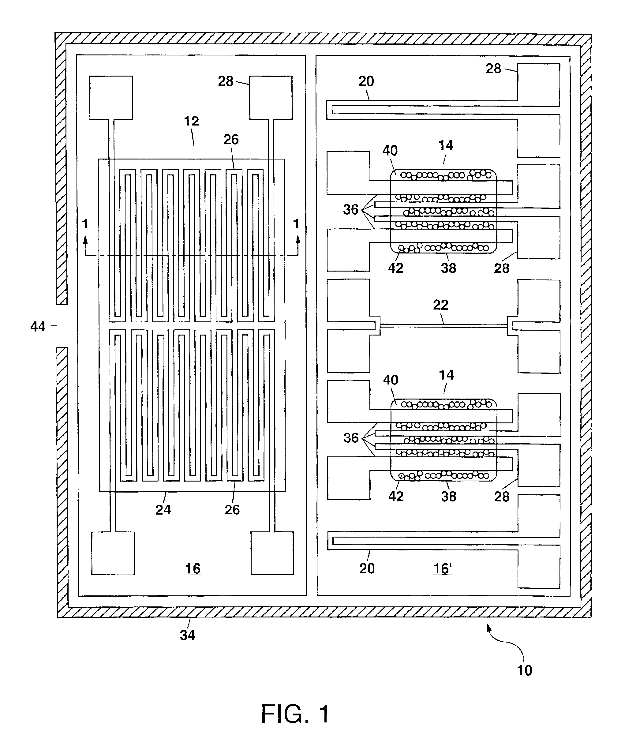
[0024]Referring to FIG. 1, there is shown the chemical-sensing apparatus 10 of the present invention. In FIG. 1, the apparatus 10 comprises a chemical preconcentrator 12 and a plurality of chemiresistors 14. The term “chemiresistor” as used herein refers to a resistor whose electrical resistance changes (e.g. increases) upon exposure to molecules of one or more chemical species. Although the preconcentrator 12 and the chemiresistors 14 are shown in FIG. 1 as being located on different substrates 16 and 16′, in other embodiments of the present invention a common substrate 16 can be used to support both the preconcentrator 12 and one or more chemiresistors 14.

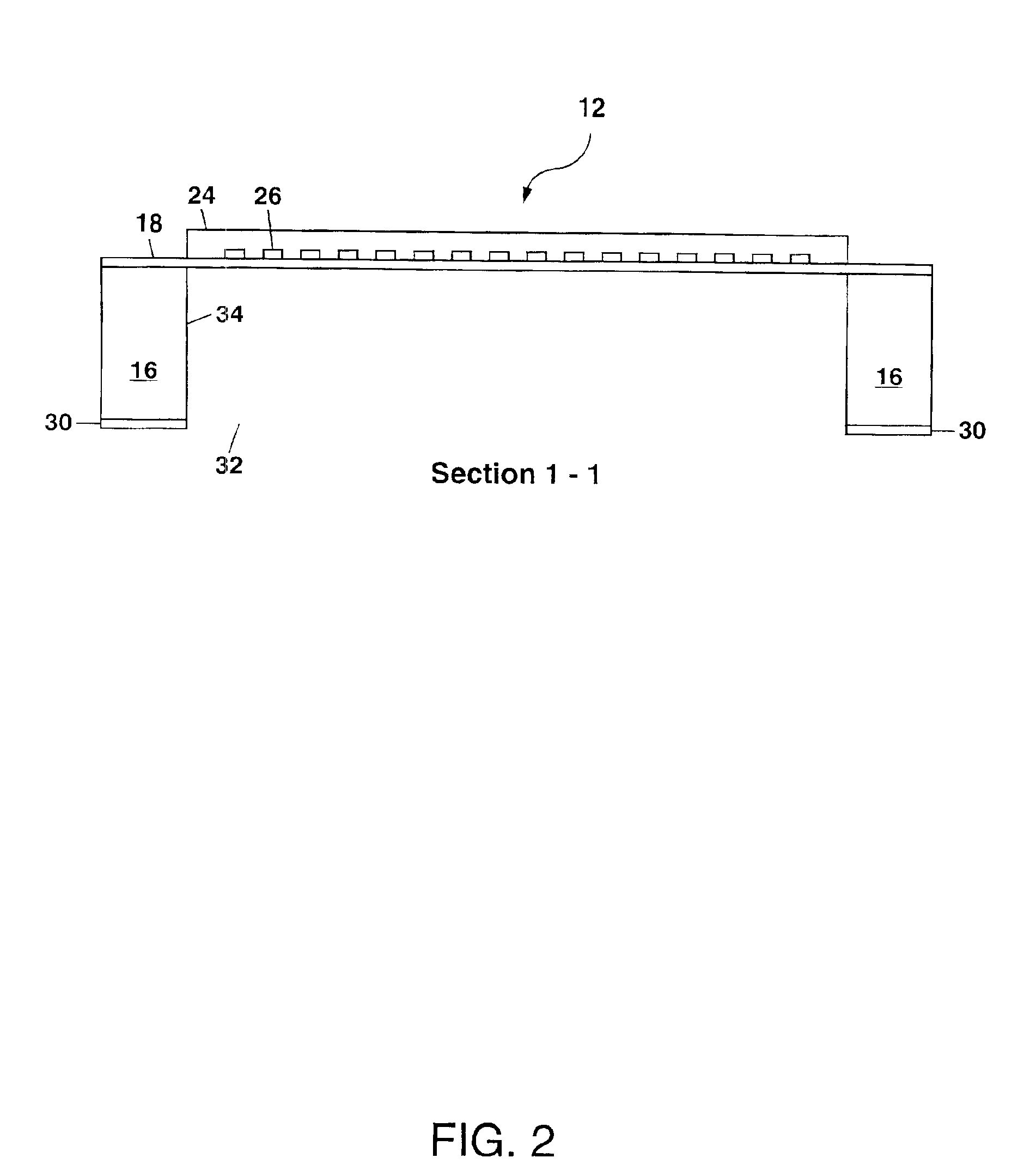
[0025]The substrates 16 and 16′ in FIG. 1 each comprise monocrystalline silicon, with a thickness of generally about 0.5 millimeter. An insulating layer 18 (e.g. silicon nitride, silicon dioxide, silicon oxynitride, silicate glass or silicon carbide) can be formed above an upper surface of each substrate 16 and 16′ to electricall...

second embodiment

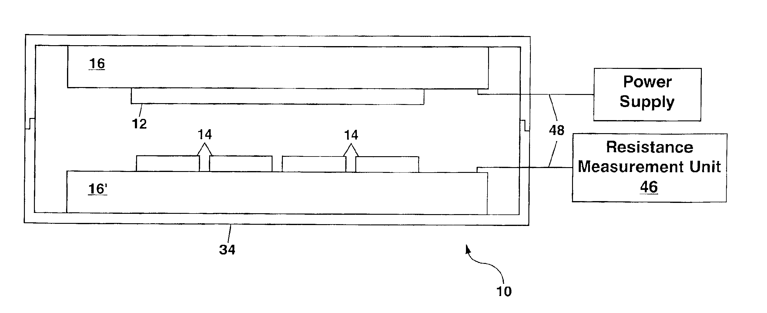
[0071]FIG. 4 schematically illustrates in cross-section view the apparatus 10 of the present invention. This embodiment of the present invention provides an increased measurement response time as compared to the embodiment of FIG. 1 since the chemiresistors 14 can be located even closer to the sorptive material 24 (e.g. ≦2 millimeters), with the chemiresistors 14 preferably facing the sorptive material 24. This embodiment of the present invention also permits each of the preconcentrator 12 and one or more chemiresistors 14 to be located on different parts of a separable housing 34 so that the preconcentrator 12 can be separated from the chemiresistors 14 if desired. This can be advantageous, for example, when one or more analytes (e.g. VOCs) are to be measured in a liquid, in the vapor above a liquid (e.g. for groundwater monitoring), or in any environment incompatible with the chemiresistors 14. This can also be advantageous when the remainder of the housing 34 contains additional ...


PUM

PropertyMeasurementUnit
Percent by volumeaaaaaaaaaa
Timeaaaaaaaaaa
Concentrationaaaaaaaaaa

Abstract

A chemical-sensing apparatus is formed from the combination of a chemical preconcentrator which sorbs and concentrates particular volatile organic chemicals (VOCs) and one or more chemiresistors that sense the VOCs after the preconcentrator has been triggered to release them in concentrated form. Use of the preconcentrator and chemiresistor(s) in combination allows the VOCs to be detected at lower concentration than would be possible using the chemiresistor(s) alone and further allows measurements to be made in a variety of fluids, including liquids (e.g. groundwater). Additionally, the apparatus provides a new mode of operation for sensing VOCs based on the measurement of decay time constants, and a method for background correction to improve measurement precision.

Description

GOVERNMENT RIGHTS[0001]This invention was made with Government support under Contract No. DE-AC04-94AL85000 awarded by the U.S. Department of Energy. The Government has certain rights in the invention.FIELD OF THE INVENTION[0002]The present invention relates in general to chemical sensing, and in particular to an apparatus that utilizes a chemical preconcentrator to extract volatile organic chemicals (VOCs) from a fluid and to generate a concentrated whiff of the VOCs for detection with one or more chemiresistors. The present invention has applications for identifying and characterizing VOCs for environmental monitoring, industrial process control, contraband detection, etc.BACKGROUND OF THE INVENTION[0003]Current methods for measuring volatile organic chemicals (VOCs) and other pollutants in the field generally involve sample collection and subsequent analysis in a well-equipped analytical chemistry laboratory. This process is time consuming and relatively expensive. For example, m...

Claims


Application Information

Patent Timeline
IPC IPC(8): G01N27/12G01N1/34G01N1/40
CPCG01N1/405G01N27/128Y10T436/25Y10T436/11Y10T29/49Y10T436/255Y10T29/49002
Inventor HUGHES, ROBERT C.MANGINELL, RONALD P.JENKINS, MARK W.KOTTENSTETTE, RICHARDPATEL, SANJAY V.
Owner NAT TECH & ENG SOLUTIONS OF SANDIA LLC
Learn More