Security device

a technology of security device and holographic plate, which is applied in the field of security plate, can solve the problems of high technological barrier for counterfeiters to overcome, difficult match of metal colours and replays,

Inactive Publication Date: 2005-06-07
DE LA RUE INT LTD
View PDF28 Cites 76 Cited by
  • Summary
  • Abstract
  • Description
  • Claims
  • Application Information

AI Technical Summary

Benefits of technology

[0009]In particular, the invention leads to a security device which will, even to the untrained eye, have an aesthetic, distinct, and novel appearance when compared with a conventional device. This approach also presents a very high technological barrier for the counterfeiter to surmount and serves to distinguish the genuine hologram from a counterfeit image even in the case where the counterfeiter has managed to sufficiently reproduce the holographic effect / microstructure either optically or by mechanical replication.
[0019]Graded structures formed in this way will have a novel attractive appearance with the copper toning down the sometimes overpowering brightness or lustre of aluminium particularly when applied to more aesthetically traditional areas such as banknotes. The backing layer could also serve to increase the chemical durability and heat resistance of the device.
[0020]In some cases, at least one of the reflection enhancing materials will extend to an edge of the substrate. However, in the preferred approach, there is no reflective material in a border region extending along an edge of the substrate. This is particularly useful in embodiments which constitute transfer foils and the like so as to minimise problems such as edge flashing and minor mis-registration or alignment of hot stamping dies.
[0022]The presence of a line structure of alternating materials, which have dissimilar radiation absorption characteristics, will also provide effects, which could be used to encode security indicia.

Problems solved by technology

These metallic colours and replays are very difficult to match by dyeing or colouring material layers.
This approach also presents a very high technological barrier for the counterfeiter to surmount and serves to distinguish the genuine hologram from a counterfeit image even in the case where the counterfeiter has managed to sufficiently reproduce the holographic effect / microstructure either optically or by mechanical replication.

Method used


Image

  • Security device
  • Security device
  • Security device

Examples


Embodiment Construction

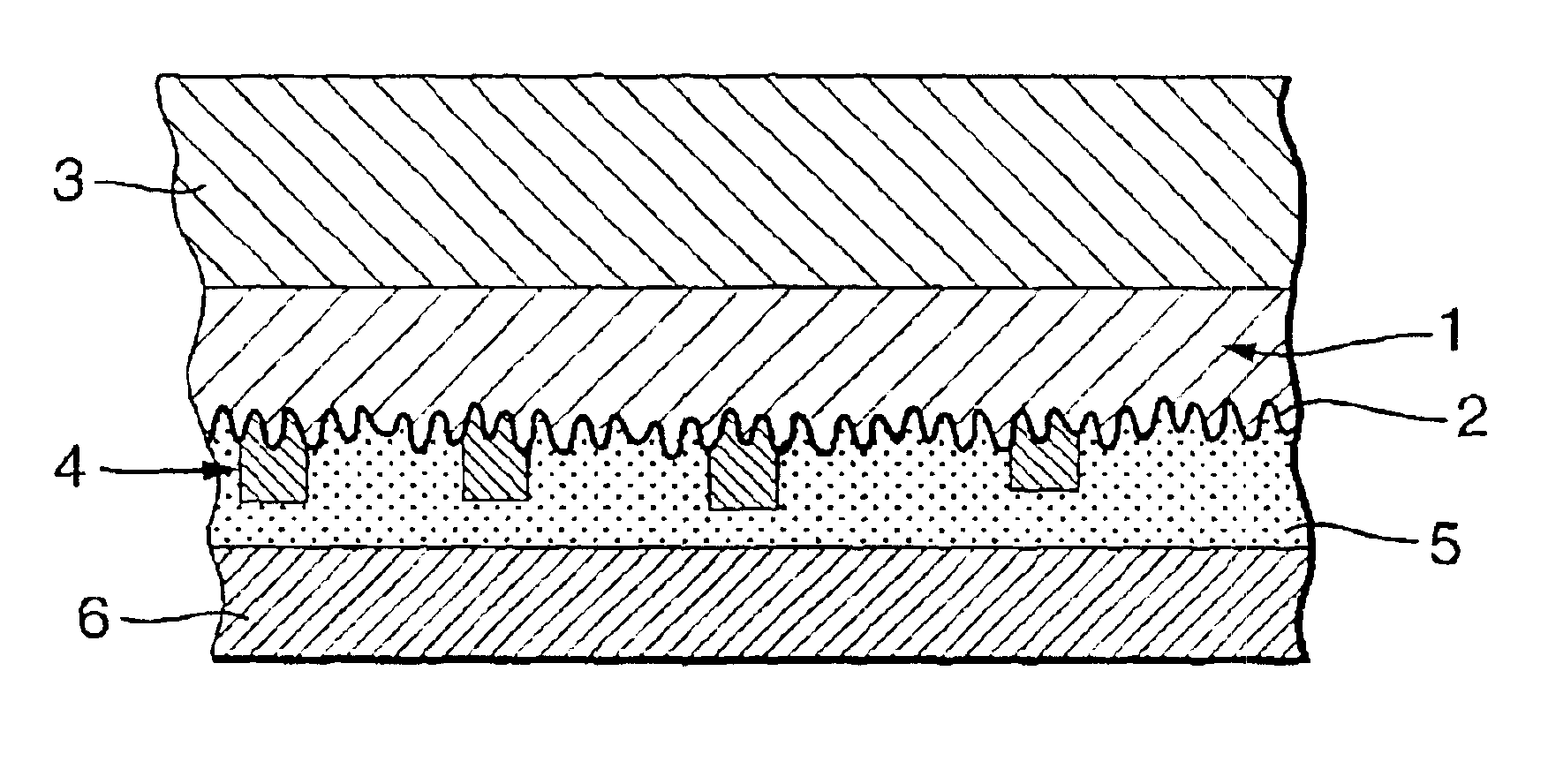
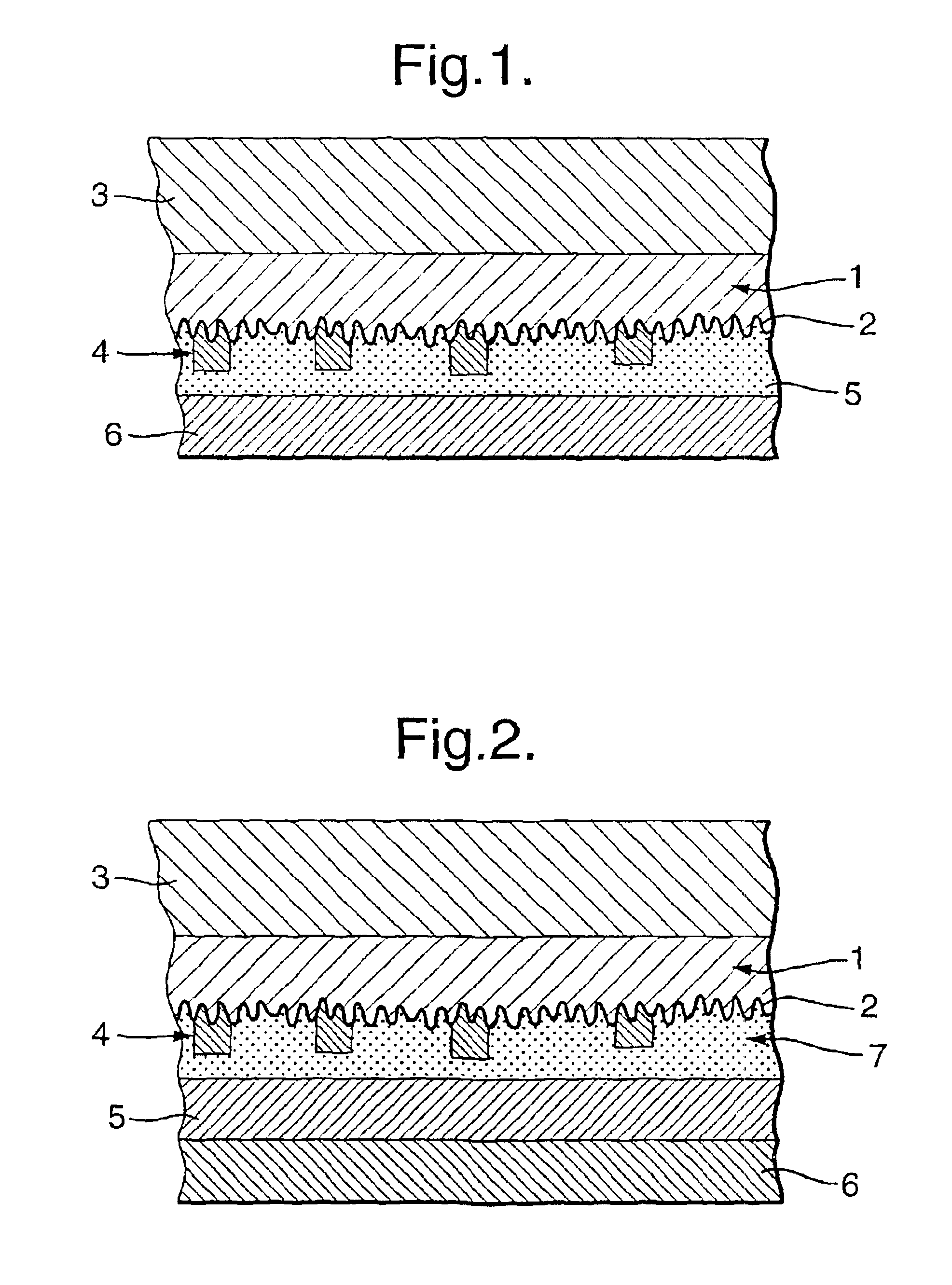
[0036]The device shown in FIG. 1 comprises a lacquer or polymeric substrate 1 having a typical thickness of 1-5 μm, into one surface of which has been embossed an optically variable microstructure 2. The substrate 1 is supported on a carrier layer 3, for example polypropylene or PET with a typical thickness of 10-50 μm and the interface between the two layers has been treated, for example, with corona discharge or wax release, so that they can be detached in a controllable way.

[0037]The surface relief 2 is vacuum coated with an aluminium layer 4, typically 20-100 nm thick, which is then partially demetallised in a designed pattern to render it partially transparent. The aluminium layer is then coated with a thicker layer of copper 5, typically 40-200 nm, and finally a 0.5-20 μm thick hot melt adhesive layer 6 (or a pressure sensitive adhesive for cold transfer) is provided on the copper layer 5.

[0038]In use, the device shown in FIG. 1 with a hot melt adhesive 6 is applied to a docum...


PUM


Abstract

A security device has a substrate formed with a surface relief defining an optically variable effect generating structure. At least two different reflection enhancing materials are provided on, or on the same side of, substrate with respect to the surface relief, whereby the optically variable effect can be viewed against a background defined by the reflection enhancing materials.

Description

BACKGROUND OF THE INVENTION[0001]1. Field of Invention[0002]The invention relates to a security device, for example for use on documents and articles of value such as bank notes and the like to reduce the risk of counterfeiting.[0003]2. Description of Related Art[0004]A common form of security device is an optically variable device, such as a hologram or diffraction grating. These devices are commonly formed as relief structures in a substrate, which is then provided with a reflective coating, for example a continuous or partial metallic layer to enhance the replay of the device. The device is then adhered to the article or document which is to be secured.[0005]With the increased sophistication of counterfeiters, it is important to develop known devices so as to enhance their security.[0006]Some examples of known security devices are described in U.S. Pat. No. 5,815,292, U.S. Pat. No. 5,742,411, U.S. Pat. No. 4,662,653 and EP-A-0395410.SUMMARY OF THE INVENTION[0007]In accordance wit...

Claims


Application Information

Patent Timeline
Patent Type & Authority Patents(United States)
IPC IPC(8): B42D15/00G03H1/02G03H1/18B41M3/14B42D15/10B44F1/12
CPCB42D25/29G03H1/02G03H1/0236G03H1/0256G03H1/18B41M3/14G03H1/0244G03H1/028G03H2001/0016G03H2001/187G03H2001/188G03H2210/53G03H2250/10G03H2250/12G03H2250/34G03H2250/36G03H2250/40G03H2250/42G03H1/0011
Inventor KAY, RALPHHOLMES, BRIAN WILLIAM
Owner DE LA RUE INT LTD
Why Eureka
Try Eureka