Magnetic head with a lamination stack to control the magnetic domain

a magnetic domain and lamination stack technology, applied in the field of magnetoresistive heads, can solve the problems of barkhausen noise and waveform instability, increase of output asymmetry, overlaid ferromagnetic film, etc., and achieve the effect of greater sensitivity and higher stability

Inactive Publication Date: 2005-06-07
HITACHI GLOBAL STORAGE TECH JAPAN LTD
View PDF11 Cites 19 Cited by
  • Summary
  • Abstract
  • Description
  • Claims
  • Application Information

AI Technical Summary

Benefits of technology

[0017]This invention provides a magnetoresistive head and a magnetic head which have greater sensitivity and higher stability compared to related art structures having the magnetic domain controlling film with a narrowed track, but maintain the same magnetic field intensity. This invention enables a GMR, CPP-GMR or TMR head and is of a magnetic domain controlling structure in which the laminated stack adjacent to a magnetoresistive stack has at least two magnetic films coupled anti-ferromagnetically through a non-magnetic film. Alternatively, it provides a GMR head operating according to a magnetic domain controlling method using the exchange coupling magnetic field of an anti-ferromagnetic film and a free layer. It also provides a magnetic domain controlling structure in which a laminated stack disposed on the end portion areas of the free layer of the magnetoresistive stack has a magnetic film which is anti-ferromagnetically coupled to the free layer through a non-magnetic film.

Problems solved by technology

When one magnetic layer in the magnetoresistive stack of an MR head is a free layer whose magnetic orientation is rotated upon receiving an external magnetic field from a magnetic recording medium, and that free layer has multiple magnetic domains, movement of magnetic domain walls occurs, causing noise.
In such case, however, drawbacks occur, such as Barkhausen noise and waveform instability, or increase of output asymmetry.
In addition to the problems relating to the dead zone area, it becomes a significant problem that the ferromagnetic film is overlaid on an upper surface of the element.
As a result, instability of the element is increased.
In addition, to suppress the instability, magnetic film 8 must be made thicker than necessary, and, as a result, a magnetic field stronger than necessary is applied over the entire free layer 2 so that sensitivity is damaged.
It is difficult to eliminate the overlay of magnetic film 8 completely due to the process employed.
Therefore, the problem arises that the end portion area of the free layer 2, which should be fixed, has sensitivity, and read drift occurs so that the record data of an adjacent track is read and the error rate is increased.
Further, there a process problem that, because the width Tw of the magnetic sensing region increases as the effective track width is broadened, the geometric track width Twr must be made smaller.
In addition, the method disclosed in Japanese Patent Laid-Open No. 282618 / 1997, Japanese Patent Laid-Open No. 53716 / 1999 or U.S. Pat. No. 5,739,990 reduces the effect on reproducing output due to the dead zone problem, but due to the weakness of the magnetic domain controlling force which is applied to the end portions widthwise in the track of the free layer disposed under the lead, read drift becomes a significant problem: side read and crosstalk deteriorate, and the effective track width is broadened.
Further, in regard to a magnetic head shown in Japanese Patent Laid-Open No. 203634 / 1999, there is a concern that, since the present head has a very narrow track width, fixing the entire surface of the free layer to be a uniform magnetic field results in lowered sensitivity, and adversely results in the absence of a magnetic domain controlling magnetic field at the end portions of the free layer, widthwise in the track where magnetic domain control is particularly necessary.
Moreover, a magnetic head shown in Japanese Patent Laid-Open No. 84527 / 2001 does not have enough coupling force since the anti-ferromagnetic film and the high coercivity film are coupled directly or through the ferromagnetic film.

Method used


Image

  • Magnetic head with a lamination stack to control the magnetic domain
  • Magnetic head with a lamination stack to control the magnetic domain
  • Magnetic head with a lamination stack to control the magnetic domain

Examples


embodiment 1

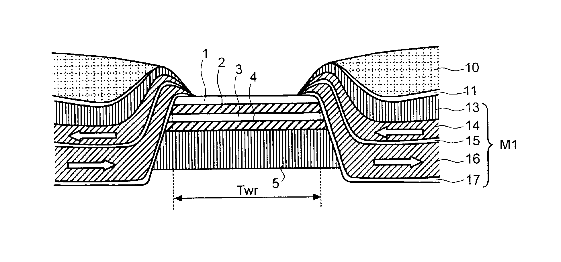
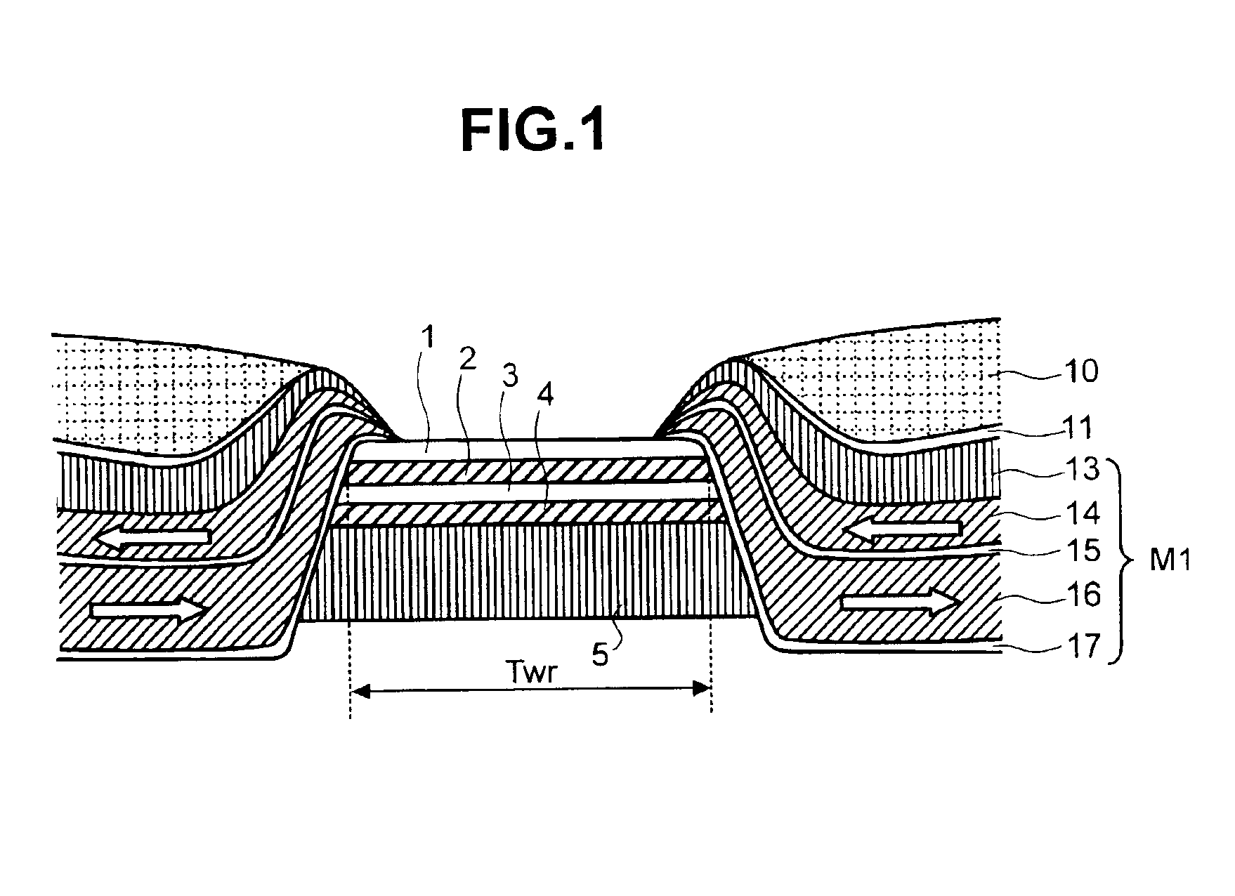
[0048]FIG. 3 shows a cross-sectional view of a CPP-GMR element according to the invention. Layers 1, 2, 3, 4, 5, 13, 14, 15, 16 and 17 shown in FIG. 3 are the same as in the structure of the embodiment 1 shown in FIG. 1. Further, the leads 10 are disposed so as to sandwich the stack which comprises 1, 2, 3, 4 and 5.

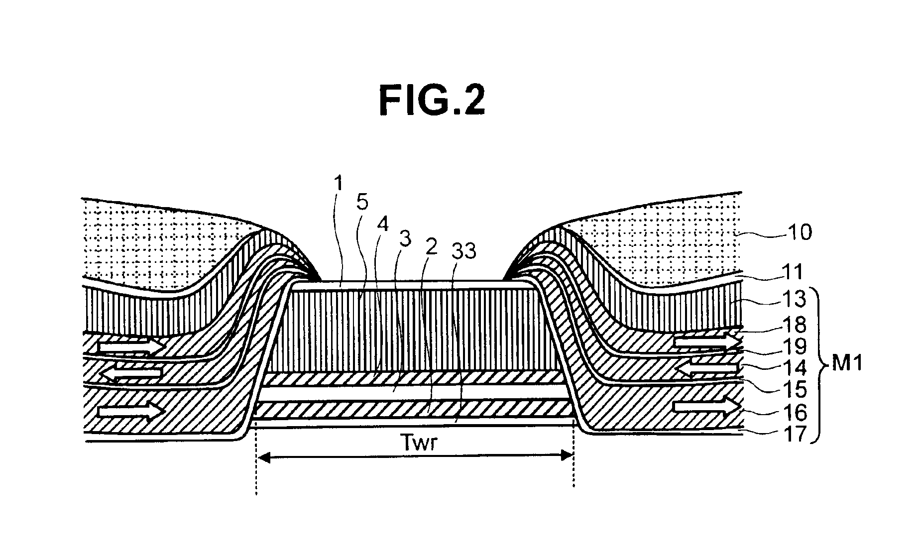
[0049]At both end portions of the stack which comprises 1-5, an insulating layer 30 is disposed, with seed layer 17 overlying the insulating layer, and magnetic layers 16 and 14 are disposed with non-magnetic film 15 between them. Nonmagnetic film 19 is disposed on magnetic film 14, and magnetic film 18 is imposed on non-magnetic film 19. An anti-ferromagnetic film 13 for fixing the magnetic orientation of the magnetic film 18 in one direction is disposed on magnetic film 18. It is, however, noted that this anti-ferromagnetic film 13 may be eliminated, for example, by properly selecting the material and thickness of the magnetic film and the non-magnetic film which is dis...

embodiment 4

[0062]In addition, when the total film thickness of the magnetic films in this embodiment and the embodiment 4 are the same, the film thickness of each magnetic film layer is reduced, since there are more magnetic films laminated with non-magnetic films in this embodiment, and since anti-ferromagnetic intensity is increased in reverse proportion to film thickness, coupling force in the lamination is strengthened and stabilized. As a result, this embodiment has the further advantage that it is less easily influenced by heat.

[0063]On the other hand, even when, as in this embodiment, more magnetic films are laminated with the non-magnetic films as compared to embodiment 4, and the film thickness is increased by just the thickness of magnetic film 22 as compared to the structure of embodiment 4, the function of the magnetic film as a side shield can be improved. These advantages can be obtained in a similar manner even when the structure of this embodiment is applied to GMR and CPP-GMR,...


PUM

PropertyMeasurementUnit
magneticaaaaaaaaaa
magnetoresistiveaaaaaaaaaa
magnetic fieldaaaaaaaaaa

Abstract

The invention provides a magnetic domain controlling structure wherein a lamination stack M1 adjacent to a magnetoresistive stack of a GMR, CPP-GMR or TMR magnetic head has at least two magnetic films 14 and 16 anti-ferromagnetically coupled through a non-magnetic film 15, or the lamination stack M2 disposed on the end portions of the free layer of the magnetoresistive stack of the GMR magnetic head has a magnetic layer anti-ferromagnetically coupled to the free layer 2 through the non-magnetic film 27. Ferromagnetic film deposition dead zone area problems and the consequent problem of film rippling in free layer portions that reduces element sensitivity are prevented, as is the problem of increased error from read drift in the magnetic field exchange coupling method, resulting in a highly stable, highly sensitive MR head with no loss of magnetic field intensity.

Description

STATEMENT AS TO RIGHTS TO INVENTIONS MADE UNDER FEDERALLY SPONSORED RESEARCH OR DEVELOPMENT[0001]Not ApplicableCROSS-REFERENCES TO RELATED APPLICATIONS[0002]Not ApplicableREFERENCE TO A “SEQUENCE LISTING,” A TABLE, OR A COMPUTER PROGRAM LISTING APPENDIX SUBMITTED ON A COMPACT DISK.[0003]Not ApplicableBACKGROUND OF THE INVENTION[0004]This invention relates to magnetoresistive heads using the magnetoresistive effect by which information is reproduced from a magnetic recording medium, and magnetic heads by which recording and reproduction are carried out.[0005]A magnetic head in a hard disk drive (HDD) provides the recording head which records information on a magnetic recording medium (hard disk) as magnetized signals and a reproducing head which reads the information recorded on the magnetic recording medium. The reproducing head is a magnetoresistive stack which comprises multiple magnetic thin films and non-magnetic thin films, and is referred to as a magnetoresistive (MR) head bec...

Claims


Application Information

Patent Timeline
Patent Type & Authority Patents(United States)
IPC IPC(8): G11B5/39
CPCB82Y10/00B82Y25/00G01R33/093G01R33/098G11B5/3912G11B5/3932G11B5/3967G11B2005/3996G11B5/3909
Inventor MORINAGA, AKIRANISHIOKA, KOICHIOHTSU, TAKAYOSHIMIYAMOTO, NORIFUMIKOJIMA, SHUICHI
Owner HITACHI GLOBAL STORAGE TECH JAPAN LTD
Why Eureka
Try Eureka