Radiological imaging apparatus and method

a technology of radiological imaging and apparatus, applied in the direction of radiological control devices, instruments, applications, etc., can solve the problems of long-term storage, time and effort involved in manual search and retrieval of physical images, and complicated process of developing images

Inactive Publication Date: 2005-06-07
CANON KK
View PDF5 Cites 30 Cited by
  • Summary
  • Abstract
  • Description
  • Claims
  • Application Information

AI Technical Summary

Benefits of technology

[0025]According to one aspect of the present invention, preferably, a radiological imaging apparatus for forming X-ray images comprises: a radiation detection unit composed of a plurality of photoelectric converters arrayed in a matrix-like formation for the purpose of detecting and converting radiation from an irradiated subject into electrical signals; a drive control unit operatively connected to the radiation detection unit for the purpose of controlling movement of the radiation detection unit; a read-out unit operatively connected to the radiation detection unit for reading the electrical signals output by the radiation detection unit; and a signal processing unit operatively connected to the rea

Problems solved by technology

On the other hand, the technique suffers from several disadvantages, including a complicated process of developing the image, the problem of long-term storage, and the time and effort involved in manual search and retrieval of the physical images.
But in reality the image as such also contains fixed pattern noise generated by the photoelectric converter circuit and the read-out circuit.
However, there are problems with the conventional methods of acquiring the dark output image (FPN).
In the former case, when the FPN is set either at shipment or prior to photography, there are two problems:
The technique of reading in the FPN just before or just after taking the X-ray image, although it solves the two problems described above, has a problem of its own:
(c) random noise generated by the photoelectric converter circuit (hereinafter referred to simply as random noise) as well as random noise generated by the read-o

Method used


Image

  • Radiological imaging apparatus and method
  • Radiological imaging apparatus and method
  • Radiological imaging apparatus and method

Examples


Embodiment Construction

[0037]Preferred embodiments of the present invention are described in detail in accordance with the accompanying drawings, in the first instance FIG. 1.

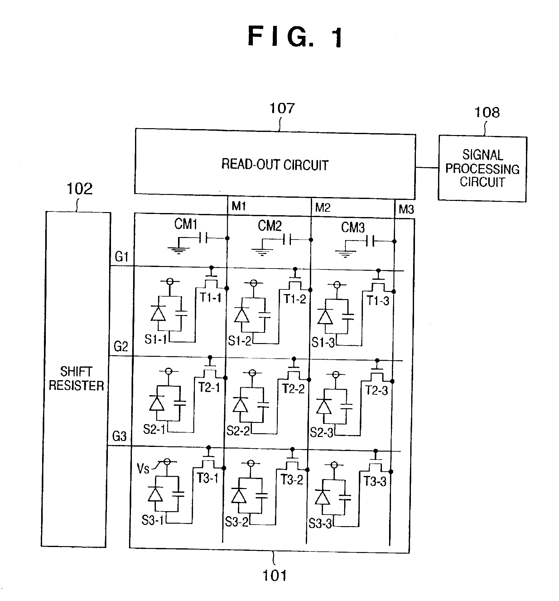
[0038]FIG. 1 is a circuit diagram showing schematically the structure of an imaging apparatus using an amorphous silicon thin film semiconductor according to one embodiment of the present invention, in which the apparatus uses photoelectric converters to take visible light and convert that light into electrical signals.

[0039]In this X-ray imaging device, an operator can select between a moving-picture mode and a still-picture mode. It should be noted that FIG. 1 does not show the fluorescent material used to convert the X-rays into visible light, and although the present embodiment is described with reference to X-ray imaging, the present invention is not limited to such but should be understood as being equally applicable to instances involving other types of radiation, such as, for example, alpha-rays, beta-rays or gamma-rays.

[0040...


PUM


Abstract

A radiological imaging apparatus and method corrects fixed pattern noise (FPN) generated within the apparatus and suppresses increases in random noise attendant upon FPN correction to provide radiological imaging having improved reliability and image quality. The apparatus has a signal processing circuit that digitizes analog output from a read-out circuit, four FPN memories for storing four dark outputs, a light memory for storing a light output after X-ray exposure of a subject, a CPU for controlling the signal processing circuit as well as FPN and light memories, and a shift resister 7 controlled by the CPU. The method involves averaging multiple dark outputs and subtracting the FPN data average so obtained from the light output which includes the X-ray imaged to enhance picture quality. Since the FPN correction uses FPN data that has been averaged over multiple dark outputs, the method also suppresses random noise generated by the FPN correction for enhanced imaging accuracy.

Description

FIELD OF THE INVENTION[0001]The present invention relates to a radiological imaging apparatus and method, and more particularly, to a radiological imaging apparatus and method used in medical X-ray equipment, industrial non-destructive testing devices and the like.BACKGROUND OF THE INVENTION[0002]With the conventional still-picture X-ray technology currently in use, the so-called film-based technique is the most prevalent. In this technique, the patient is exposed to X-rays and the X-rays that pass through the body are then exposed onto a sheet of film. The film has the function of displaying and recording information, and is widely used throughout the world due to its capacity to be enlarged, its high degree of gradation, its light weight and ease of handling. On the other hand, the technique suffers from several disadvantages, including a complicated process of developing the image, the problem of long-term storage, and the time and effort involved in manual search and retrieval o...

Claims


Application Information

Patent Timeline
IPC IPC(8): A61B6/00G01N23/04G01N23/02
CPCA61B6/583A61B6/585G01N23/046G01N23/04G01N2223/419
Inventor ENDO, TADAO
Owner CANON KK
Why Eureka
Try Eureka