System and method of generating a finite element mesh for a threaded fastener and joining structure assembly

a technology of finite element mesh and threaded fastener, which is applied in the field of finite element can solve the problems of fatigue failure, difficult to reproduce the effect of other loading factors, and difficult to position strain gage at thread interface, etc., and achieves the effect of facilitating fatigue analysis of threaded fasteners and joining structures, reducing design time and related expenses, and good quality three dimensional

Inactive Publication Date: 2005-06-07
FORD GLOBAL TECH LLC
View PDF14 Cites 44 Cited by
  • Summary
  • Abstract
  • Description
  • Claims
  • Application Information

AI Technical Summary

Benefits of technology

[0010]One advantage of the present invention is that an improved system and method of generating a finite element mesh for a threaded fastener and joining structure is provided that produces a good quality three dimensional mesh while considerably reducing design time and related expenses. Another advantage of the present invention is that the system and method utilizes parametric automated design in light of predetermined engineering and manufacturing criteria. Yet another advantage of the present invention is that the system and method facilitates fatigue analysis of the threaded fastener and joining structure early in the design process. Still another advantage of the present invention is that the system and method supports computer-aide...

Problems solved by technology

For example, a fatigue failure, such as a crack in a thread root, may occur in a threaded portion of the joining structure.
However, it is extremely difficult to position a strain gage at the thread interface between the threaded fastener and the joining structure and still be able to recreate ...

Method used


Image

  • System and method of generating a finite element mesh for a threaded fastener and joining structure assembly
  • System and method of generating a finite element mesh for a threaded fastener and joining structure assembly
  • System and method of generating a finite element mesh for a threaded fastener and joining structure assembly

Examples


Embodiment Construction

)

[0020]The design of a fastener and joining structure, and in particular the design of a threaded fastener and joining structure for use as an assembly on a vehicle, is achieved according to the present invention with a generic, parametric driven design method. Advantageously, this system and method allows flexibility in design of the threaded fastener and joining structure and engineering analysis of the design in a fraction of the time required using conventional design methods, since the design is automatically evaluated against rules in a knowledge base. Various computer-based tools are integrated into a single user interface to achieve this enormous time and expense savings, including solid modeling, parametric design, automated studies and a knowledge-based engineering library.

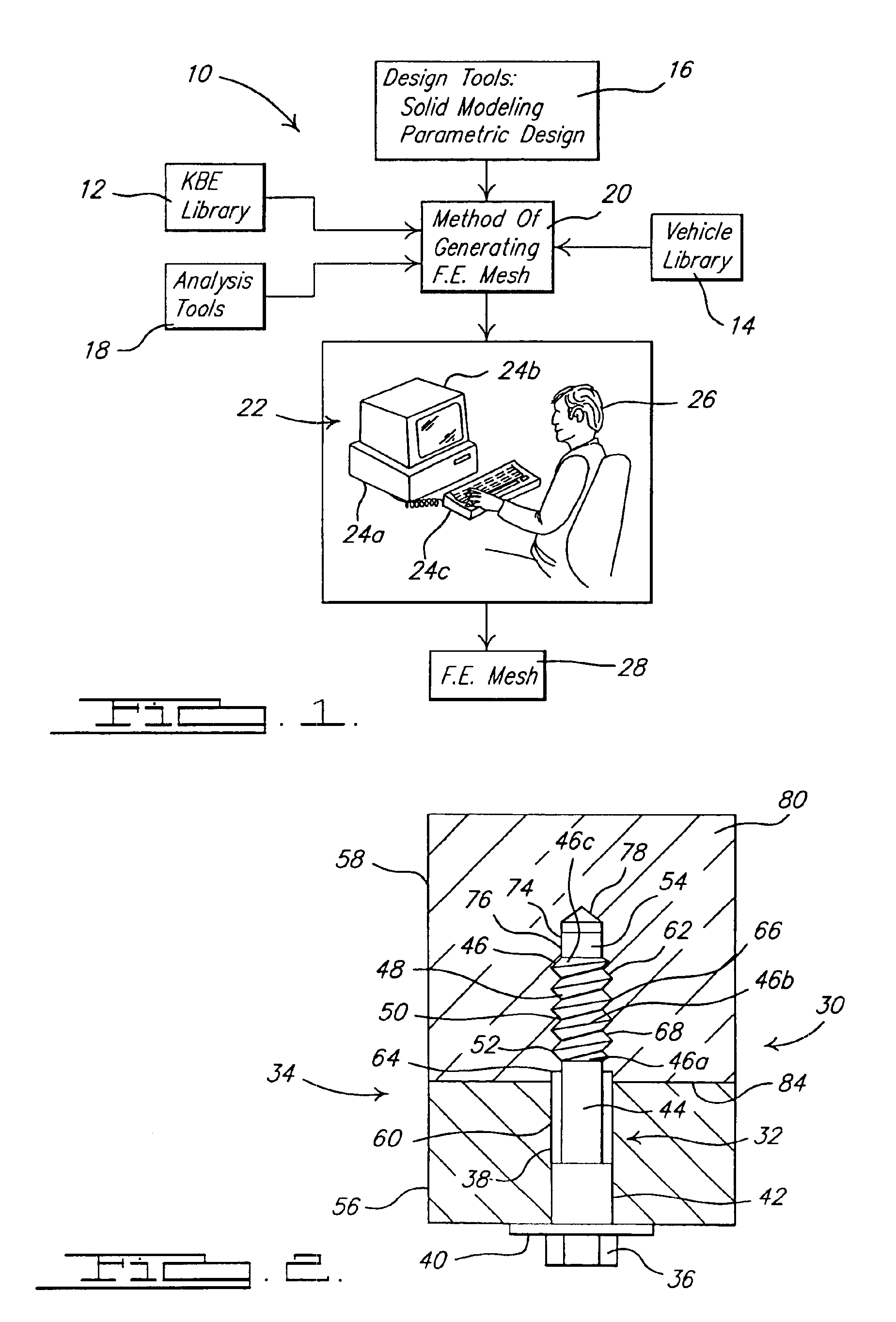
[0021]Referring to the drawings and in particular FIG. 1, the tools 10 used by a system and method for generating a finite element mesh for a threaded fastener and joining structure, according to the pre...


PUM


Abstract

A system and method of generating a finite element mesh for a threaded fastener and joining structure assembly includes a computer system for generating a mesh model of the threaded fastener and joining structure assembly by creating nodes and elements for each non-threaded portion of the threaded fastener and joining structure assembly using cylindrical coordinates and creating nodes and elements for each threaded portion of the threaded fastener and joining structure assembly using helical coordinates. The system and method also includes a user evaluating the mesh model of the threaded fastener and joining structure assembly using finite element analysis and evaluating a result of the finite element analysis using a visualization software program and a computer system. The system and method further includes a user predicting a stress of the threaded fastener and joining structure assembly from the evaluation of the result of the finite element analysis.

Description

BACKGROUND OF THE INVENTION[0001]1. Field of the Invention[0002]The present invention relates generally to finite element analysis of a threaded fastener and, more specifically, to a system and method of generating a finite element mesh for a threaded fastener and joining structure assembly.[0003]2. Description of the Related Art[0004]Fastener design, and in particular the design of a threaded fastener, has advanced to a state in which computer-aided design techniques are frequently incorporated in the development and analysis of a threaded fastener and a structure joined together by the threaded fastener, such as two blocks. Computer-aided design is especially beneficial in analyzing a stress in a joining structure resulting from the load transfer through contacting threads of the threaded fastener and mating surfaces in the joining structure. For example, a fatigue failure, such as a crack in a thread root, may occur in a threaded portion of the joining structure. The ability to p...

Claims


Application Information

Patent Timeline
IPC IPC(8): G06F9/455G06F17/50
CPCG06F17/5095G06F17/5018G06F30/15G06F30/23
Inventor DEJACK, MICHAEL A.STRENSKI, DAVID G.KINNEY, PAUL R.
Owner FORD GLOBAL TECH LLC
Why Eureka
Try Eureka