Ejector-type depressurizer for vapor compression refrigeration system

a refrigeration system and ejector-type technology, which is applied in the direction of refrigeration components, machines/engines, lighting and heating apparatus, etc., can solve the problems of reduced ejector efficiency, insufficient increase of compressor intake pressure, and insufficient reduction of compressor power consumption, etc., to achieve high ejector efficiency

Inactive Publication Date: 2005-06-14
DENSO CORP
View PDF20 Cites 22 Cited by
  • Summary
  • Abstract
  • Description
  • Claims
  • Application Information

AI Technical Summary

Benefits of technology

[0008]The present invention addresses the above disadvantage. Thus, it is an objective of the present invention to provide an ejector-type depressurizer for a vapor compression refrigeration system capable of maintaining relatively high ejector efficiency regardless of a flow rate of refrigerant passing through a pressurizer arrangement of the ejector-type depressurizer.
[0009]To achieve the objective of the present invention, there is provided an ejector-type depressurizer for a vapor compression refrigeration system. The vapor compression refrigeration system includes a compressor that compresses refrigerant, a radiator that cools the refrigerant compressed by the compressor, and an evaporator that vaporizes refrigerant. The ejector-type depressurizer includes a nozzle arrangement, a pressurizer arrangement and a refrigerant passing zone varying means. The nozzle arrangement converts pressure energy of the refrigerant suppli...

Problems solved by technology

However, when the energy conversion efficiency of the ejector, i.e., the ejector efficiency becomes relatively low, the intake pressure of the compressor cannot be sufficiently increased by the ejector, so that the power consumption of the compressor cannot be sufficiently reduced.
At this time, when a flow rate of the refrigerant passing through the refrigerant passage of the pressurizer arrangement is excessively large with respect to the passage cross sectional size (or area) of the refrigerant passage in the pressurizer arrang...

Method used


Image

  • Ejector-type depressurizer for vapor compression refrigeration system
  • Ejector-type depressurizer for vapor compression refrigeration system
  • Ejector-type depressurizer for vapor compression refrigeration system

Examples


first embodiment

(First Embodiment)

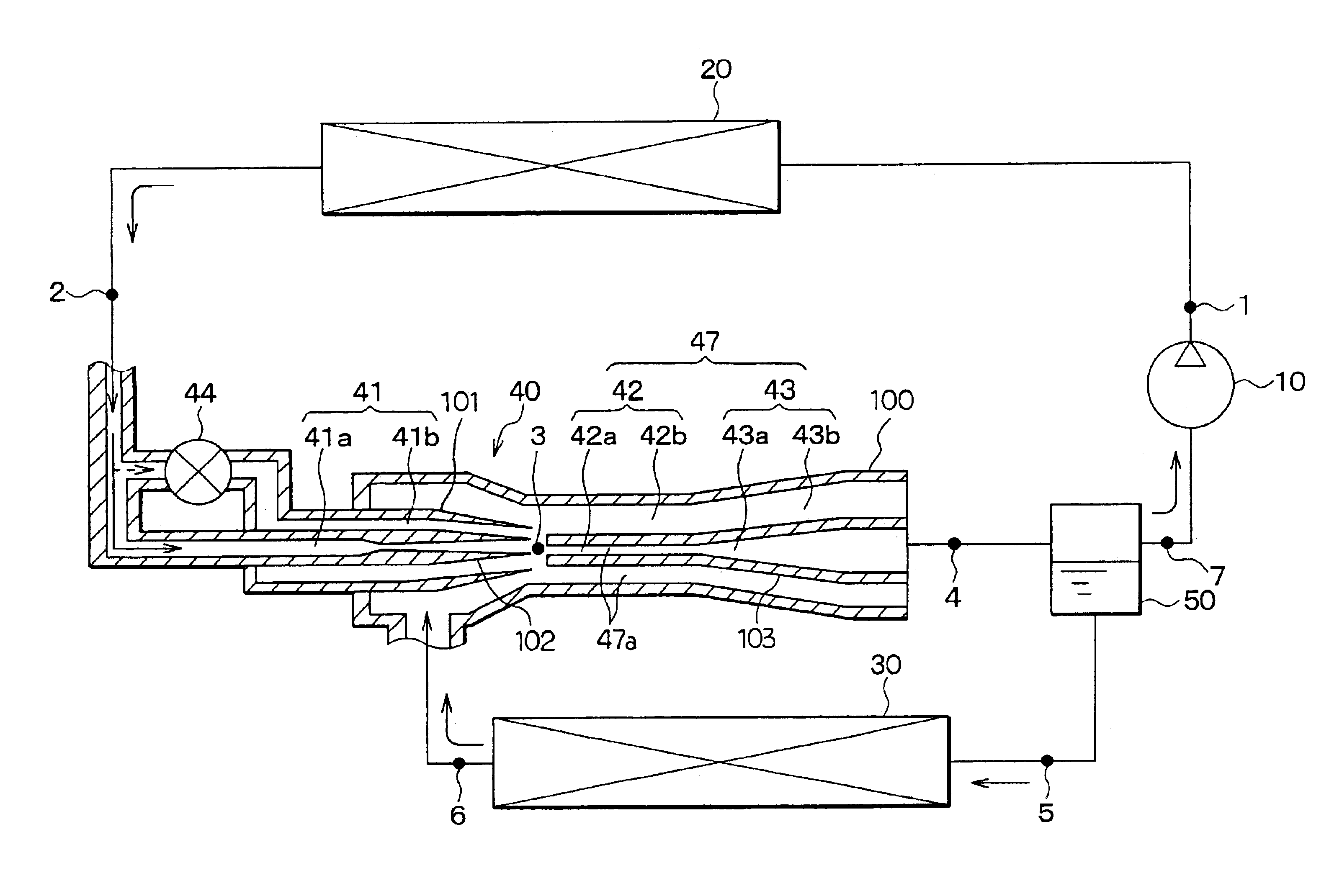
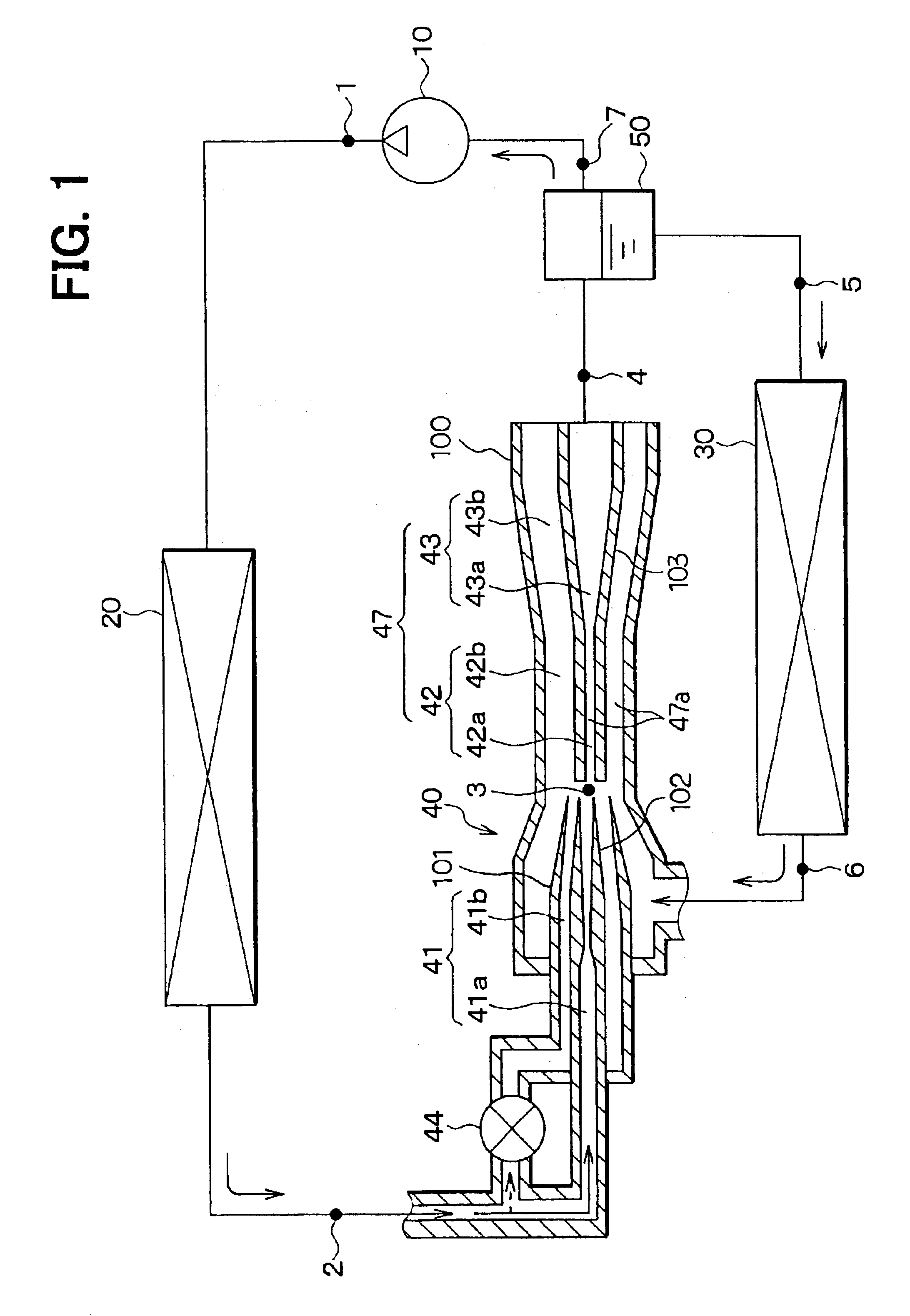
[0039]In a first embodiment of the present invention, an ejector-type depressurizer, i.e., an ejector for an ejector cycle of the present invention is embodied in a vehicle air conditioning system. FIG. 1 schematically shows an ejector cycle according to the first embodiment.

[0040]With reference to FIG. 1, a compressor 10 is a variable displacement compressor of a known type, which is powered by a drive engine of a vehicle to draw and compress refrigerant. Alternatively, the compressor 10 can be an electric compressor driven by an electric motor. A radiator 20 is a high pressure side heat exchanger. In the radiator 20, heat is exchanged between the refrigerant discharged from the compressor 10 and outside air located outside a passenger compartment of the vehicle to cool the refrigerant.

[0041]In the first embodiment, chlorofluorocarbon is used as the refrigerant, so that refrigerant pressure in the radiator 20 is normally kept equal to or less than the critical pre...

second embodiment

(Second Embodiment)

[0061]In the first embodiment, the valve 44 is arranged on the upstream side of the outer nozzle passage part 41b. Alternatively, in a second embodiment of the present invention, the valve 44 is arranged on an upstream side of the inner nozzle passage part 41a, as shown in FIG. 5. Control operation of the valve 44 is the same as that of the first embodiment and will not be described for the sake of simplicity.

[0062]With this arrangement, in the present embodiment, the refrigerant discharged from the nozzle arrangement 41 always has the annular refrigerant flow. Thus, the refrigerant flow discharged from the nozzle arrangement 41 always has the relatively large contact surface area to maintain relatively large drawing force of the ejector 40 for drawing the vaporized refrigerant from the evaporator 30. Furthermore, it should be noted that the valve 44 can be arranged on the upstream side of each of the outer nozzle passage part 41b and the inner nozzle passage part...

third embodiment

(Third Embodiment)

[0063]In a third embodiment of the present invention, the pressurizer arrangement 47 (i.e., the mixer arrangement 42 and the diffuser arrangement 43) is formed as a single tubular body. Furthermore, as shown in FIGS. 6A and 6B, the pressurizer arrangement 47 (i.e., the mixer arrangement 42 and the diffuser arrangement 43) has a variable mechanism (variable iris diaphragm means) 45, which is similar to a shutter (iris diaphragm) of a camera and is capable of varying an aperture size, i.e., a passage cross sectional size of the refrigerant passage (more specifically, the variable refrigerant passing zone of the refrigerant passage) 47a. FIG. 6A shows a state where the refrigerant flow rate is relatively small, and thus the aperture size of the variable mechanism 45 is reduced. FIG. 6B shows a state where the refrigerant flow rate is relatively large, and thus the aperture size of the variable mechanism 45 is increased.

[0064]In this way, without providing the multi-tu...


PUM


Abstract

In an ejector-type depressurizer, a nozzle arrangement converts pressure energy of refrigerant supplied from a radiator into velocity energy to depressurize and expand the refrigerant, and a pressurizer arrangement mixes the refrigerant discharged from the nozzle arrangement with the refrigerant drawn from an evaporator and converts the velocity energy of the refrigerant discharged from the nozzle arrangement into pressure energy to increase the pressure of the mixed refrigerant discharged from the pressurizer arrangement. The pressurizer arrangement includes a refrigerant passage that conducts the refrigerant supplied from the nozzle arrangement and the refrigerant supplied from the evaporator, and the refrigerant passage includes a refrigerant passing zone, through which the refrigerant from the nozzle arrangement and the refrigerant from the evaporator mainly pass during operation of the ejector-type depressurizer. A cross sectional size of the refrigerant passing zone of the refrigerant passage is variable.

Description

CROSS REFERENCE TO RELATED APPLICATION[0001]This application is based on and incorporates herein by reference Japanese Patent Application No. 2002-140621 filed on May 15, 2002.BACKGROUND OF THE INVENTION[0002]1. Field of the Invention[0003]The present invention relates to an ejector-type depressurizer for a vapor compression refrigeration system, i.e., an ejector for an ejector cycle.[0004]2. Description of Related Art[0005]As is known in the art, an ejector for an ejector cycle is a kinetic pump which includes a nozzle arrangement and a pressurizer arrangement (see JIS Z8126 Number 2.1.2.3). The nozzle arrangement depressurizes and expands refrigerant to generate high velocity refrigerant flow. In the mixer arrangement, the high velocity refrigerant, which is discharged from the nozzle arrangement, entrains and draws refrigerant from an evaporator, so that the drawn refrigerant (drawn flow) and the discharged refrigerant (drive flow) are mixed, and velocity energy of the discharged...

Claims


Application Information

Patent Timeline
IPC IPC(8): F04F5/46F04F5/04F04F5/00F25B41/00
CPCF04F5/04F04F5/461F25B41/00F25B2500/01F25B2341/0012F25B2341/0013B60H2001/3298
Inventor OGATA, GOTATAKEUCHI, HIROTSUGU
Owner DENSO CORP
Why Eureka
Try Eureka