Imaging ultrasound transducer temperature control system and method using feedback

a technology of ultrasound transducer and temperature control system, which is applied in the direction of ultrasonic/sonic/infrasonic diagnostics, instruments, applications, etc., can solve the problems of less penetration ability of high frequency ultrasonic waves, less well defined received images, and greater penetration depth of frequency ultrasonic waves. to achieve the effect of reducing the temperature of imaging ultrasonic transducers

Inactive Publication Date: 2005-06-14
KONINK PHILIPS ELECTRONICS NV
View PDF34 Cites 154 Cited by
  • Summary
  • Abstract
  • Description
  • Claims
  • Application Information

AI Technical Summary

Benefits of technology

[0033]One object of the present invention is to provide a system and method for reducing the temperature of an imaging ultrasonic transducer in general, and the patient contacting surface in specific, without merely turning the transducer off.
[0034]Another object of the present invention is to provide a system and method for reducing the temperature of an imaging ultrasonic transducer which may work either as a replacement for the conventional active or passive heat dissipation systems or as an adjunct to them.
[0035]Yet another object of the present invention is to provide a system and method by which an operator of an imaging ultrasonic transducer system may control the manner in which the ultrasonic transducer system changes parameters in order to cool the ultrasonic transducer.

Problems solved by technology

However, high frequency ultrasonic waves have less penetrating ability because their energy is absorbed and scattered by soft tissues.
On the other hand, lower frequency ultrasonic waves have a greater depth of penetration, but the received images are much less well defined.
Obviously, these harmonics do not generate as clear a picture as the harmonics from contrast agents.
Furthermore, since the harmonics are generated inside the body, they only pass through the fat layer once, rather than twice.
However, it the velocity of the blood how being measured exceeds the Nyquist Limit (half the PRF), the ultrasonic readings become inaccurate.
However, higher frequencies and greater acoustic intensities cause the ultrasonic transducer to heat up, and there are regulatory limits (and practical limits) on the surface temperature of an ultrasonic probe when interacting with a subject.
The fundamental limitation is that, for most transducers, even if heat is spread uniformly on the external case surfaces, it only takes a few watts of transducer driving power to cause the average transducer surface temperature to become unacceptable either with respect to the patient or the sonographer.
In these cases, and particularly for small transducers having small surface areas, one may find that one is unable to operate at the allowable acoustic intensity limit because of excessive temperatures.
Thus, no imaging or sensing is being performed by the ultrasonic transducer in the '356 patent.
When this occurs, the power circuits stop providing power to the ultrasonic transducer.
However, such a feedback control system can be inappropriate for ultrasonic imaging / measuring applications.
Although abruptly turning off the power during a therapeutic ultrasonic session may not be damaging, abruptly turning off the power during an imaging / measuring session can be potentially dangerous (e.g., a sudden blackout during a surgical procedure).
Even when not dangerous, turning off the image makes the diagnosis and analysis of image data difficult.

Method used


Image

  • Imaging ultrasound transducer temperature control system and method using feedback
  • Imaging ultrasound transducer temperature control system and method using feedback
  • Imaging ultrasound transducer temperature control system and method using feedback

Examples


Embodiment Construction

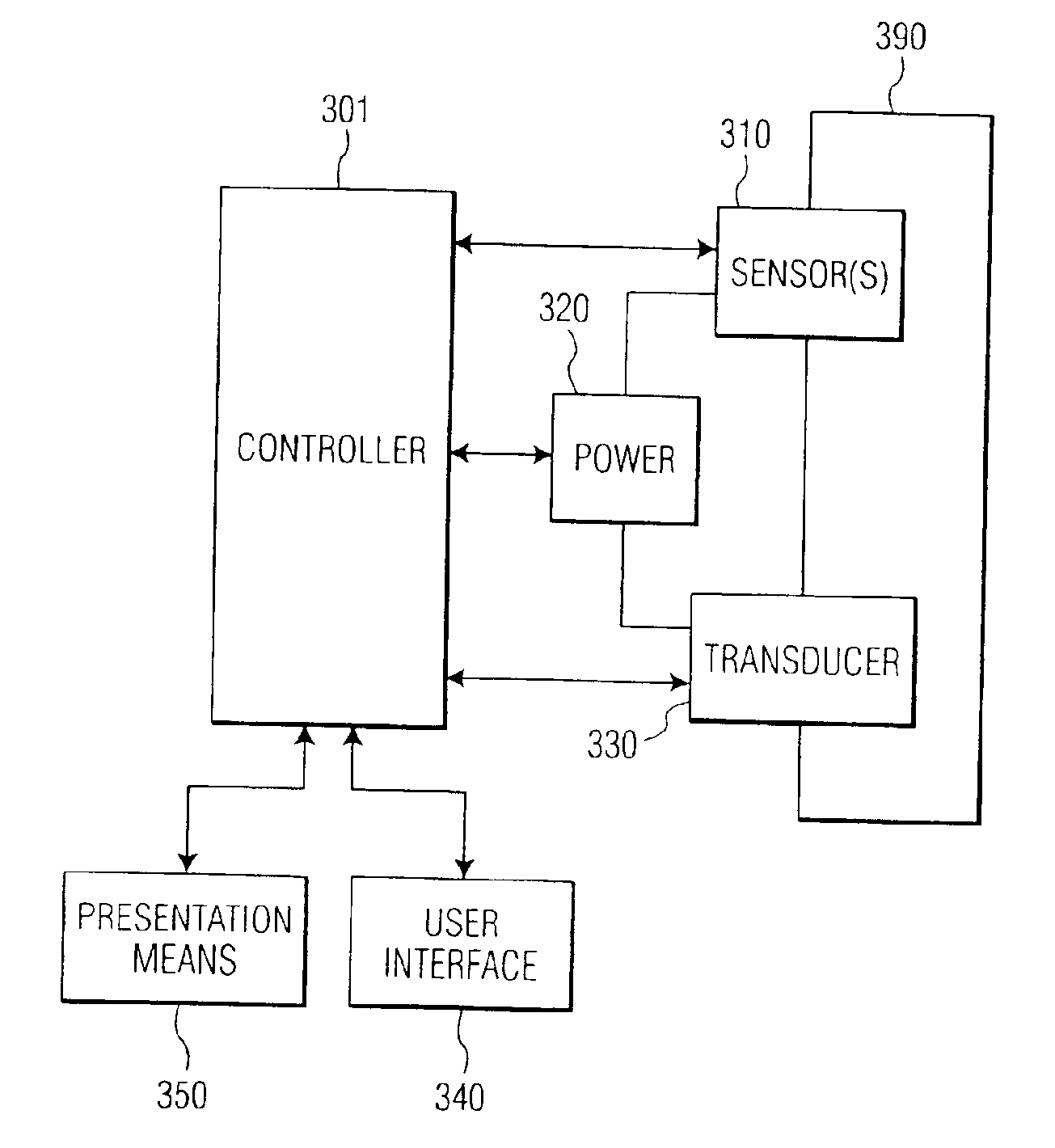
[0049]The present invention is directed to a novel system and method of controlling the radiant heat from the patient contact surface of an ultrasonic transducer. Although the details of implementation may be different in different embodiments, the present invention is not limited to any particular type of ultrasonic transducer or any particular mode of imaging and / or data analysis. The presently preferred embodiments of the present invention control the temperature of the transducer face by changing operating system parameters based on feedback from temperature sensing elements placed in the transducer. Which operating parameters are changed and the manner in which the chosen parameters change depends upon the imaging mode, the type of heat dissipation system being used (if any), the particular ultrasonic system, etc. In addition, these choices may be preset by the construction of the ultrasonic system, under the control of the ultrasonic system user, or a combination of the two.

[0...


PUM

PropertyMeasurementUnit
frequencyaaaaaaaaaa
frequencyaaaaaaaaaa
frequencyaaaaaaaaaa

Abstract

A system and method for controlling the heat of an ultrasonic transducer is disclosed. In the presently preferred embodiments, the system and method controls the temperature of the transducer by changing operating system parameters based on feedback from temperature sensing elements placed in the transducer. The chosen mutable system parameters may be preset by the construction of the ultrasonic system, under the control of the ultrasonic system user, or a combination of the two. In several exemplary embodiments, the one or more mutable system parameters are altered by an amount proportionate to the difference between the current temperature and a preferred operating temperature. In another exemplary embodiment, the system switches to a lower power imaging mode when the temperature feedback indicates a threshold temperature has been reached.

Description

RELATED APPLICATIONS[0001]This patent application is a continuation of U.S. patent application Ser. No. 10 / 268,261, filed Oct. 10, 2002, now issued U.S. Pat. No. 6,709,392, which is hereby incorporated by reference, and from which this application claims the benefit of priority under 35 U.S.C. §120.BACKGROUND OF THE INVENTION[0002]1. Field of the Invention[0003]The invention relates generally to the field of imaging ultrasonic medical transducer assemblies, and, specifically, to an apparatus and method for cooling the transducer.[0004]2. Description of the Related Art[0005]Ultrasonic medical transducers are used to observe the internal organs of a patient. The ultrasonic range is described essentially by its lower limit: 20 kHz, roughly the highest frequency a human can hear. The medical transducers emit ultrasonic pulses which echo (i.e., reflect), refract, or are absorbed by structures in the body. The reflected echoes are received by the transducer and these received signals are ...

Claims


Application Information

Patent Timeline
Patent Type & Authority Patents(United States)
IPC IPC(8): A61B8/00G01N29/24
CPCA61B8/00A61B8/546A61B8/481
Inventor SALGO, IVANPESZYNSKI, MICHAELMILLER, DAVID
Owner KONINK PHILIPS ELECTRONICS NV
Why Eureka
Try Eureka