Methods for transferring supercritical fluids in microelectronic and other industrial processes

a technology of supercritical fluids and manufacturing processes, applied in the direction of water supply installation, cleaning using liquids, transportation and packaging, etc., can solve the problems of resist deformation and pattern collapse, low water solubility, and difficulty in ensuring the effect of fluid flow

Inactive Publication Date: 2005-06-14
MICELL TECH INC
View PDF25 Cites 85 Cited by
  • Summary
  • Abstract
  • Description
  • Claims
  • Application Information

AI Technical Summary

Benefits of technology

[0021]displacing at least a portion of the first supercritical fluid from the vessel with the pressure of the second, preferably fluid while maintaining the interface therebetween.
[0022]An aspect of the present invention is a method of cleaning a microelectronic device, comprising the steps of: providing a substrate having a surface portion to be cleaned, providing a densified carbon dioxide cleaning composition, the composition comprising carbon dioxide and a cleaning adjunct, the cleaning adjunct selected from the group consisting of cosolvents, surfactants, etchants, oxidants, chelants, stabilizers and co

Problems solved by technology

In some cases, the use of water in these evolving processes has resulted in challenges whereby deleterious effects of water and byproducts carried by water have been seen.
Capillary forces present in the aqueous drying of imaged resist patterns can result in resist deformation and pattern collapse.
This problem becomes particularly serious as lithography techniques move toward smaller image nodes with larger aspect ratios.
However, while the absence of surface tension and the accessible critical temperature and pressure of CO2 have been touted as positives factors for this drying approach, the relatively low solubility of water in the supercritical phase has also been described as a challenge that may necessitate the use of chemical adjuncts to increase the transport capacity of the fluid.
In both the direct and indirect drying methods the choice of surfactants and co-solvents is limited by what is described as compatibility issues leading to resist damage.
Another problem with drying of surfaces on microelectronic substrates (e.g. photoresist coated semiconductor wafers, MEMS, opto-electronic devices, photonic devices, flat panel displays, etc) is the complete removal of aqueous processing, cleaning or rinsing solutions without leaving a residue, commonly referred to as a drying watermark.
In many microel

Method used


Image

  • Methods for transferring supercritical fluids in microelectronic and other industrial processes
  • Methods for transferring supercritical fluids in microelectronic and other industrial processes
  • Methods for transferring supercritical fluids in microelectronic and other industrial processes

Examples


example 1

Treatment of a Coated Wafer with Liquid Carbon Dioxide

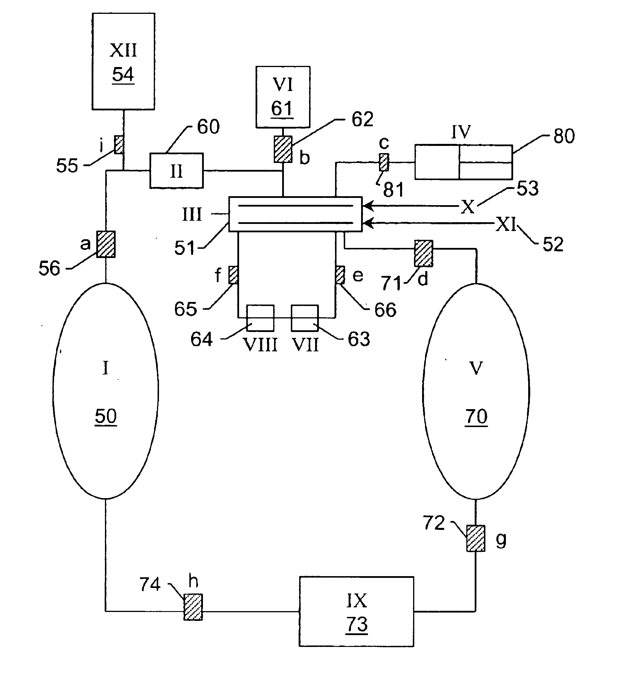
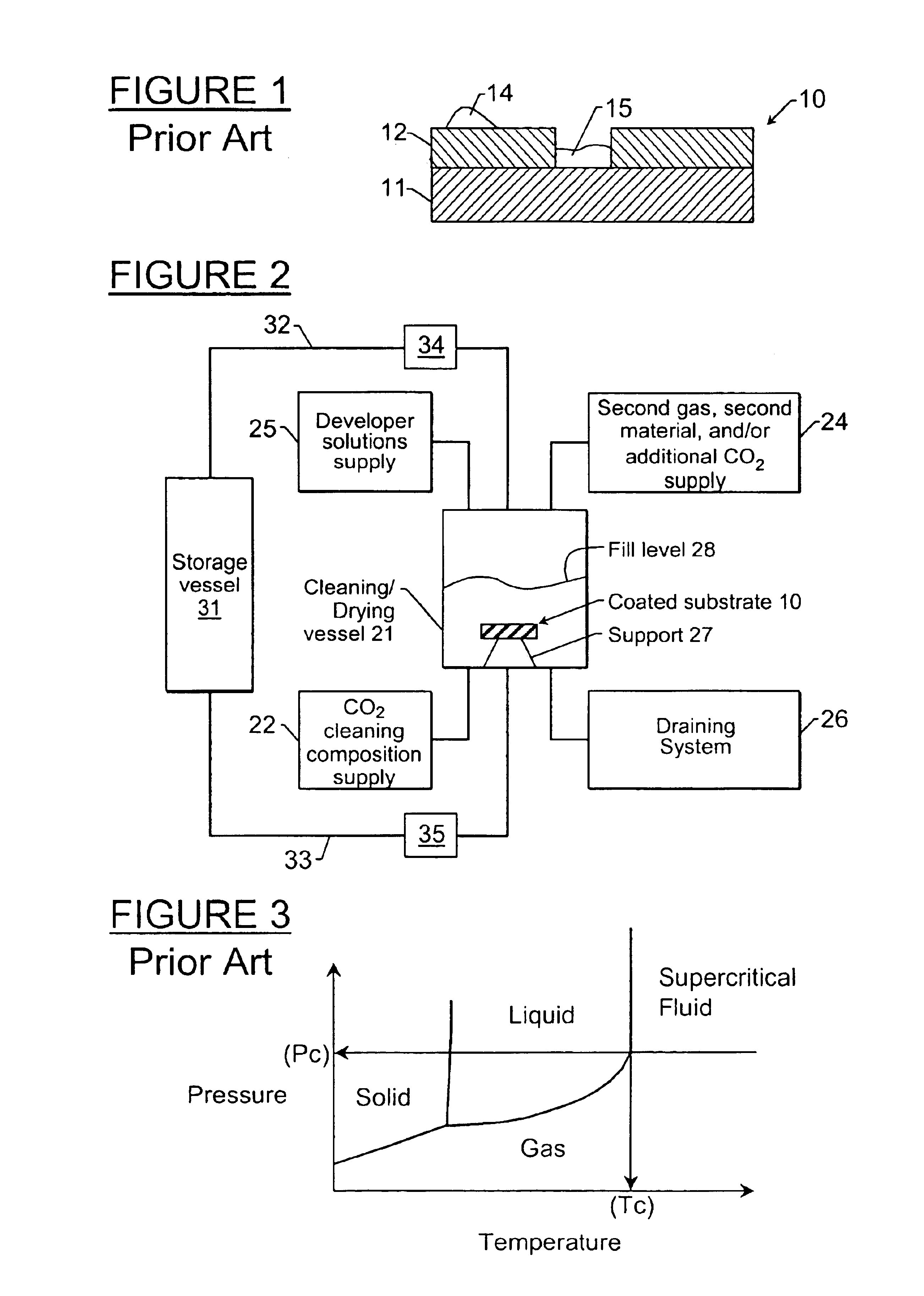
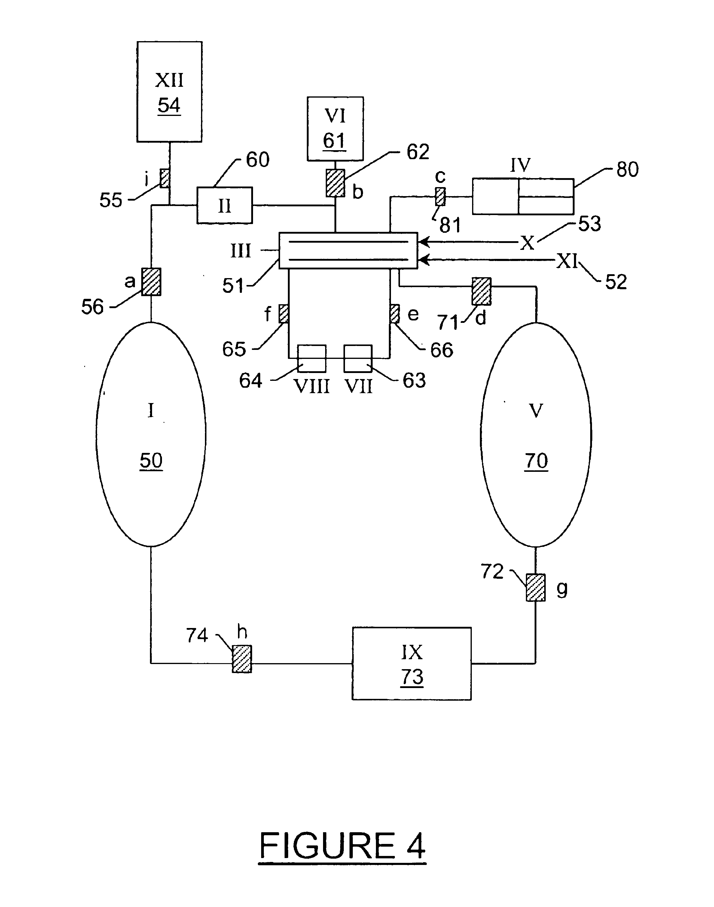
[0128]Liquid CO2 was added to a high-pressure vessel that contained a piece of a PHS coated silicon wafer until the wafer was completely submerged in liquid CO2. A mixture that contained liquid CO2 and IPA, 2% IPA by volume, (alternatively any CO2-miscible, hydrophilic solvent, or any hydrophilic / CO2-philic surfactant) was added to the high-pressure vessel that contained the piece of PHS coated silicon wafer submerged in liquid CO2. No damage to the wafer was observed. The system was mixed for 15 minutes. There was still no damage to the wafer. A secondary gas (helium or nitrogen) was added to the top of the high-pressure vessel. The liquid CO2 / IPA mixture was drained under the pressure of the secondary gas to prevent boiling at the liquid / gas / wafer interface. There was no damage to the wafer after the system was drained with a secondary gas. The system was rinsed with pure liquid CO2 and was then drained as mentioned above. Ther...

example 2

Treatment of a Coated Wafer with Liquid Carbon Dioxide

[0129]Liquid CO2 at its saturated vapor pressure was added to a high-pressure vessel that contained a piece of a PHS coated silicon wafer until the wafer was completely submerged in liquid CO2. A mixture that contained liquid CO2 and IPA, 2% IPA by volume, (alternatively any CO2-miscible, hydrophilic solvent, or hydrophilic / CO2-philic surfactant) was added to the high-pressure vessel that contained the piece of PHS coated silicon wafer submerged in liquid CO2. No damage to the wafer was observed. The liquid CO2 mixture was drained from the high-pressure vessel to another high-pressure vessel containing predominantly liquid CO2 at saturated vapor pressure by first opening a valve connecting the vapor side of both vessels then by opening a valve connecting the liquid side of both vessels. The liquid was drained by force of gravity as the first vessel was positioned substantially above the second to allow for complete drainage. No d...

example 3

Treatment of a Coated Wafer with Liquid and Supercritical CO2

[0130]Liquid CO2 was added to a high-pressure vessel that contained a piece of a PHS coated silicon wafer until the wafer was completely submerged in liquid CO2. A mixture that contained liquid CO2 and IPA, 2% IPA by volume, (alternatively any CO2-miscible, hydrophilic solvent or surfactant that increased the carry capacity of CO2 for water) was added to the high-pressure vessel that contained the piece of PHS coated silicon wafer submerged in liquid CO2. No damage to the wafer was observed. After a period of time sufficient to remove the substantial majority of the water from the surface of the wafer, the liquid mixture was diluted with pure liquid CO2 to effect approximately 5 liquid turnovers in the drying chamber. Heat was then added to the liquid CO2 causing a transition to the supercritical phase. The chamber containing the wafer is then drained and vented by maintaining the temperature of fluid and gas above the cr...


PUM

PropertyMeasurementUnit
Fractionaaaaaaaaaa
Percent by massaaaaaaaaaa
Weightaaaaaaaaaa

Abstract

A method of displacing a supercritical fluid from a pressure vessel (e.g., in a microelectronic manufacturing process), with the steps of: providing an enclosed pressure vessel containing a first supercritical fluid (said supercritical fluid preferably comprising carbon dioxide); adding a second fluid (typically also a supercritical fluid) to said vessel, with said second fluid being added at a pressure greater than the pressure of the first supercritical fluid, and with said second fluid having a density less than that of the first supercritical fluid; forming an interface between the first supercritical fluid and the second fluid; and displacing at least a portion of the first supercritical fluid from the vessel with the pressure of the second, preferably fluid while maintaining the interface therebetween.

Description

RELATED APPLICATIONS[0001]This application continuation-in-part of U.S. patent applications Ser. No. 09 / 951,247 filed Sep. 13, 2001 now U.S Pat No. 6,602,351, Ser. No. 09 / 951,092, filed Sep. 13, 2001 now U.S. Pat. No. 6,613,157, Ser. No. 09 / 951,249 filed Sep. 13, 2001 now U.S. Pat. No. 6,641,678 and Ser. No. 09 / 951,259 filed Sep. 13, 2001 now U.S. Pat. No. 6,596,093, all of which are continuations in part of U.S. patent application Ser. No. 09 / 932,063, filed Aug. 17, 2001, now issued as U.S. Pat. No. 6,562,146, which in turn claims the benefit of U.S. Provisional Patent Application Ser. No. / 60 / 269,026, filed Feb. 15, 2001;[0002]and this application further claims the benefit of U.S. Provisional Patent Application Ser. No. 60 / 442,867, filed Jan. 27, 2003;[0003]the disclosures of all of which are incorporated by reference herein in their entirety.FIELD OF THE INVENTION[0004]The present invention concerns methods and apparatus for transferring fluids during manufacturing processes, su...

Claims


Application Information

Patent Timeline
IPC IPC(8): B08B7/00H01L21/00H01L21/02H01L21/306B05D1/18B81B3/00B81C1/00
CPCB08B7/0021H01L21/67028H01L21/02101H01L21/02063B05D1/18B05D2401/90H01L21/67017Y10T137/0324B08B3/00B08B5/00C03C23/00
Inventor DEYOUNG, JAMES P.MCCLAIN, JAMES B.GROSS, STEPHEN M.WAGNER, MARK I.
Owner MICELL TECH INC
Why Eureka
Try Eureka