Color-coded armored cable

Active Publication Date: 2005-06-14
SOUTHWIRE CO LLC
View PDF43 Cites 101 Cited by
  • Summary
  • Abstract
  • Description
  • Claims
  • Application Information

AI Technical Summary

Benefits of technology

[0009]In accordance with important aspects of the invention, the longevity of retention of the non-patterned color coating to the observable outer surface of the metallic sheath is enhanced by incorporating the synergistic combination of features of an abraded metallic surface, a precise thickness of color coating, a polyethylene based lubricant of specific volumetric percentage incorporated into the color coating, and a specific profile shape and optimum number of convolutions of the helically wound metallic strip forming the cable sheath. An additional translucent coating is optionally disposed over the color coating.
[0010]In accordance with further aspects of the invention, the so-constructed color-coded armored cable is provided with a coating, preferably conductive, disposed over the interior surface of the cable sheath to facilitate fabrication of color-coated metal strips which form the sheath and to minimize damage

Problems solved by technology

Unfortunately, prior color-coding techniques for armored cable, and the resulting color-coded armored cable, have substantial disadvantages associated with them.
Additionally, the requirement that the color coating leave portions of the surface of the metal sheath exposed is not only unnecessary from an electrical standpoint, but results in a needless processing expense and could cause the sheath to be susceptible to corrosion.
Furthermore,

Method used


Image

  • Color-coded armored cable
  • Color-coded armored cable
  • Color-coded armored cable

Examples


Embodiment Construction

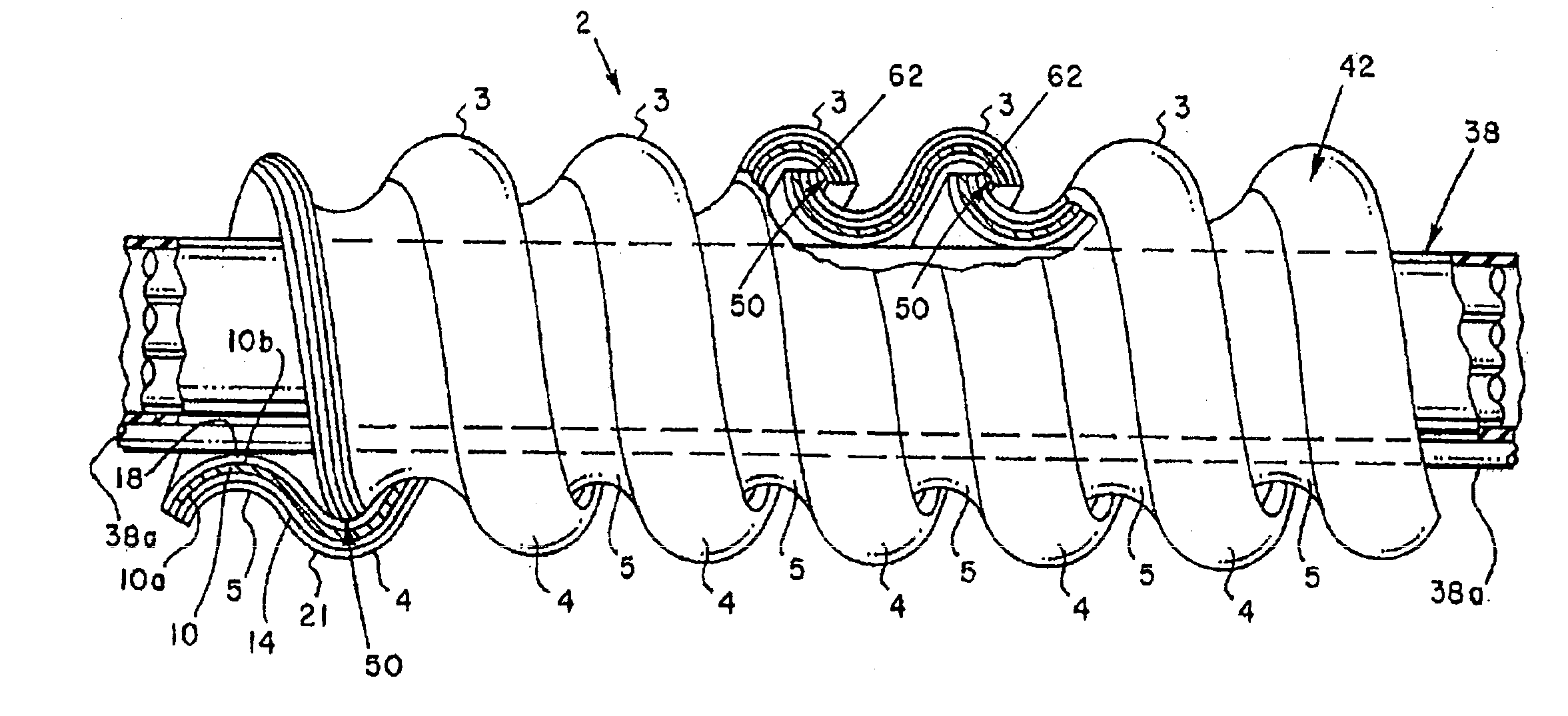
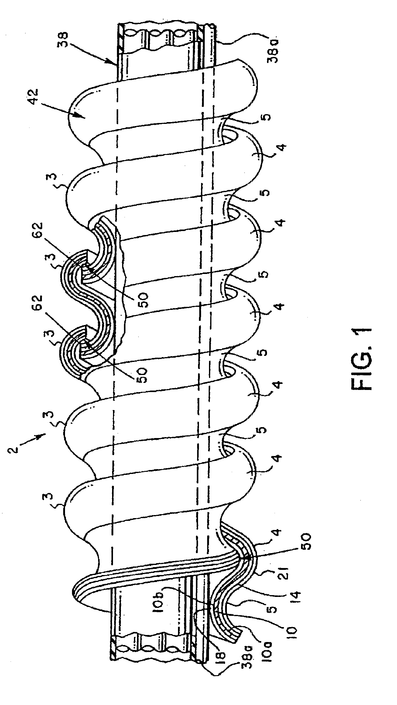
[0025]Referring initially to FIG. 1, there is depicted a new and improved color-coded armored cable assembly 2 in accordance with the present invention. The cable assembly 2 comprises a color coded tubular metallic sheath 42 enclosing a set 38 of insulated conductors extending through the interior passageway defined by the sheath 42. In the case of a Type AC armored cable, the conductor set 38 includes an uninsulated ground or bond wire 38a operable, if desired, to make contact with an inner wall surface of sheath 42, particularly an electrically conductive contact when this surface is uncoated or coated with a conductive coating. However, the improvements of this invention are also applicable to other types of metal clad armored cable, including Type MC armored cable, in which the ground wire is an insulated conductor. The sheath 42 is formed of a helically wound, uniquely contoured metal strip 10, preferably of aluminum, which has been color coated in a manner subsequently describ...


PUM


Abstract

A color coded flexible armored cable includes a tubular sheath formed from a metal strip having a continuous, non-patterned, non-conductive color coating applied to the entirety of an abraded outer surface of the strip. The color coating is of a predetermined precise thickness and includes a polyethylene based wax lubricant in a percent by volume of about 0.45 to 0.55. The strip is formed into helical convolutions having a cross-sectional shape which provides for overlap and interlocking of adjacent convolutions and contact between adjacent convolutions along a helical line such that, upon bending the sheath, the convolutions remain in contact at a trailing edge of one convolution and the inner surface of an adjacent convolution in a way such that the color coating is not scraped off of the outer surface of the sheath. The sheath is preferably formed such that the number of convolutions per unit length of sheath is maximum for sheath flexibility and retention of the coating on the outer surface of the sheath.

Description

BACKGROUND OF INVENTION[0001]The present invention relates to the general field of visually coded electrical conductors and cable, more particularly to the field of visually coded armored cable, and even more particularly to a new and improved version of color-coded armored cable.[0002]Visual coding of electrical conductors and cable to distinguish their electrical properties, intended use, or other characteristics has been a long time practice. Such coding has typically used, for example, alpha-numeric stamping, varied marking patterns, or specific colors or color combinations, to respectively distinguish the electrical characteristics, application, or the like, of the conductors or cable. Such coding is represented by industry practices and documented in patents dating back at least as early as the 1900s. Examples of these patents are U.S. Pat. No. 951,147, issued Mar. 8, 1910; U.S. Pat. No. 2,106,048, issued Jan. 18, 1938; U.S. Pat. No. 3,720,747, issued Mar. 13, 1973; and U.S. P...

Claims


Application Information

Patent Timeline
IPC IPC(8): H01B7/18H01B7/20H01B7/36H02G3/04
CPCH02G3/0468H01B7/366H01B7/184
Inventor GRANT, JR., EDWIN H.HARDIN, WILLIAM K.MCCARDEL, DAVID B.MILLER, RICHARD R.
Owner SOUTHWIRE CO LLC
Why Eureka
Try Eureka