Electric resistance measuring connector and measuring device and measuring method for circuit board electric resistance

a technology of electric resistance and connector, which is applied in the direction of resistance/reactance/impedence, measurement instrument housing, instruments, etc., can solve the problems of inability to use circuit boards, inability to increase the yield of products, and difficulty in managing the above, etc., to achieve high connection reliability, high precision, and high sensitivity pressure-sensitive conductivity

Inactive Publication Date: 2005-06-14
ISC CO LTD
View PDF9 Cites 36 Cited by
  • Summary
  • Abstract
  • Description
  • Claims
  • Application Information

AI Technical Summary

Benefits of technology

[0047]According to the connector for measurement of electric resistance of the above-described construction, both movable electrode and stationary electrode in the composite electrode sheet are electrically connected to one electrode to be inspected when the front-side anisotropically conductive elastomer layer is pressed by every electrodes to be inspected in the circuit board to be inspected, the electric resistance of which should be measured. In addition, since the stationary electrodes are formed in a state coming into no contact with the movable electrodes, one of the movable electrode and stationary electrode electrically connected to the electrode to be inspected is used as an electrode for current supply, and the other is used as an electrode for voltage measurement, whereby an electric resistance as to the circuit board to be inspected can be measured with high precision.
[0048]The movable electrodes in the composite electrode sheet are supported movably in the thickness-wise direction of the insulating sheet body, whereby the movable electrodes are moved in the thickness-wise direction according to the projected heights of the electrodes to be inspected when the front-side anisotropically conductive elastomer layer is pressed by every electrodes to be inspected, so that the irregularity-absorbing ability in each of the front-side anisotropically conductive elastomer layer and back-side anisotropically conductive elastomer layer formed on the front surface and back surface of the composite electrode sheet can be effectively utilized. In addition, the thickness of each of the front-side a

Problems solved by technology

Therefore, the circuit board becomes impossible to be used.
Under such circumstances, the electric resistance measurement cannot be performed on all circuit boards to be provided as products, and so, so-called sampling inspection has to be performed, and after all, the yield of the products cannot be increased.
However, when a measurement of an electric resistance between electrodes is performed as to the circuit boards used in such flip chip mounting methods by means of the electric resistance-measuring apparatus of the above-described constructions (i) to (iii), the following problems are involved.
However, it is extremely difficult to manage the above, and after all, it is very difficult to produce an electric resistance-measuring apparatus for measuring the electric resistance of a circuit board having small-sized electrodes at a high density.
However, such an electric resistance-measuring apparatus is great in measurement error range, and so it is difficult to perform electric resistance measurement as to a circuit board low in electric resistance between electrodes with high precision.
Further, when electric resistance measurement is performed as to a circuit board to be inspecte

Method used


Image

  • Electric resistance measuring connector and measuring device and measuring method for circuit board electric resistance
  • Electric resistance measuring connector and measuring device and measuring method for circuit board electric resistance
  • Electric resistance measuring connector and measuring device and measuring method for circuit board electric resistance

Examples


example 1

[0189]An electric resistance-measuring apparatus for circuit boards was produced under the following conditions in accordance with the construction illustrated in FIGS. 16 and 17.

(1) Upper-side Adapter:

[One-side Circuit Board for Inspection on One Side]

[0190]Shape and dimensions of inspection electrodes:[0191]circle, 0.12 mm in diameter.

[0192]Pitch between inspection electrodes:[0193]0.25 mm.

[Connector for Measurement of Electric Resistance]

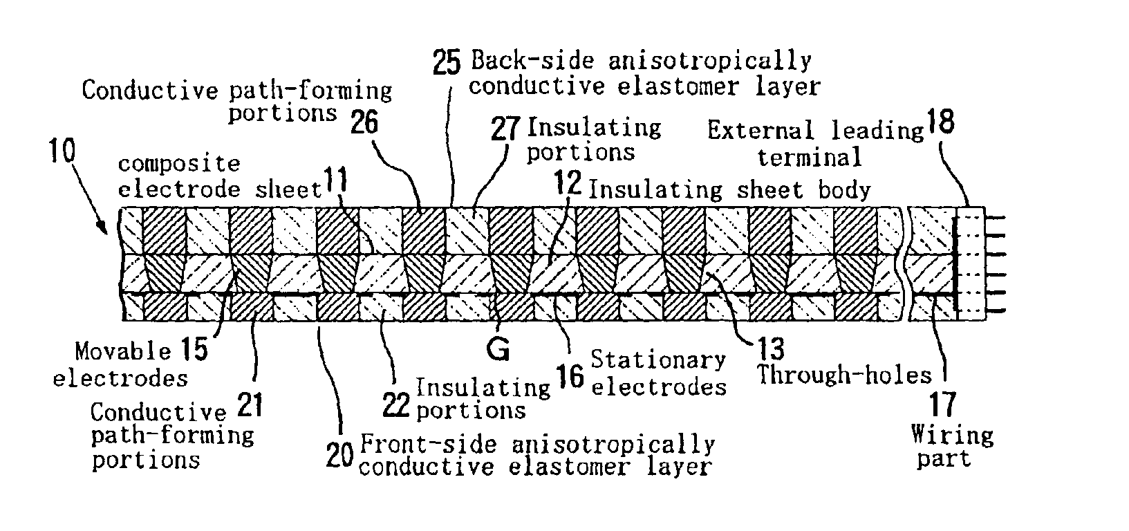
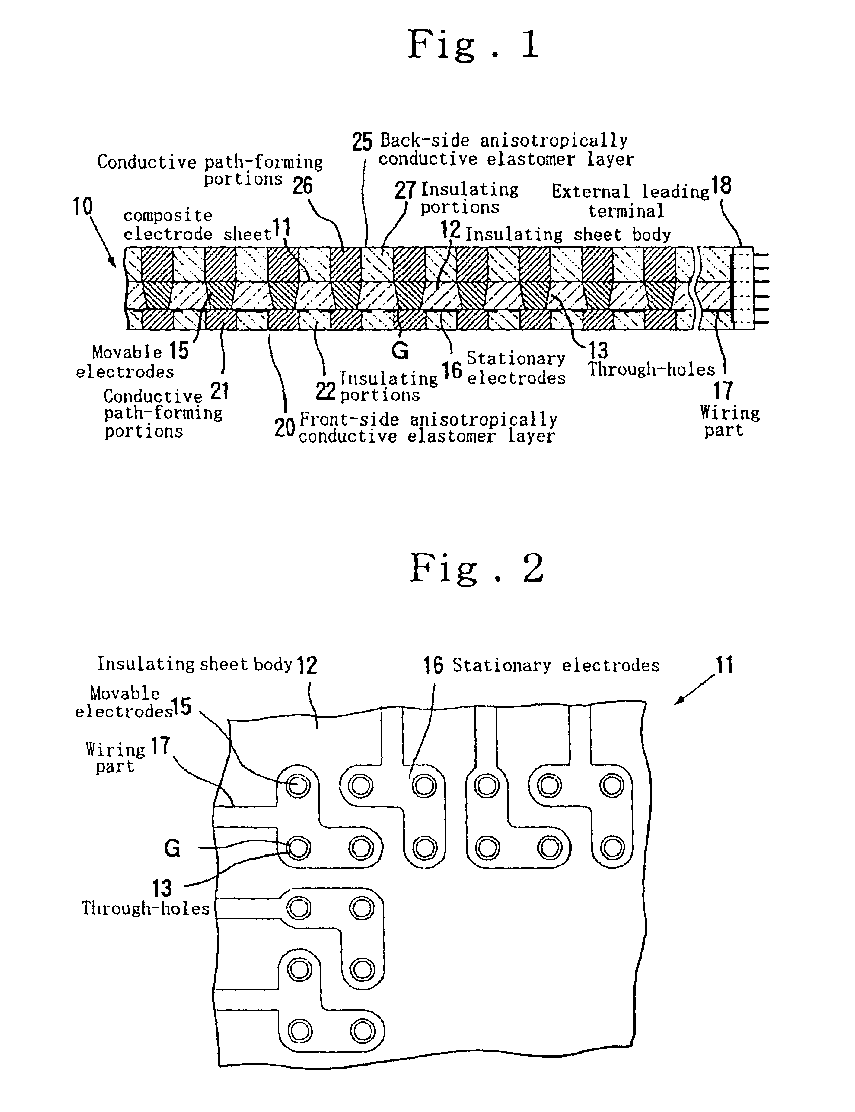
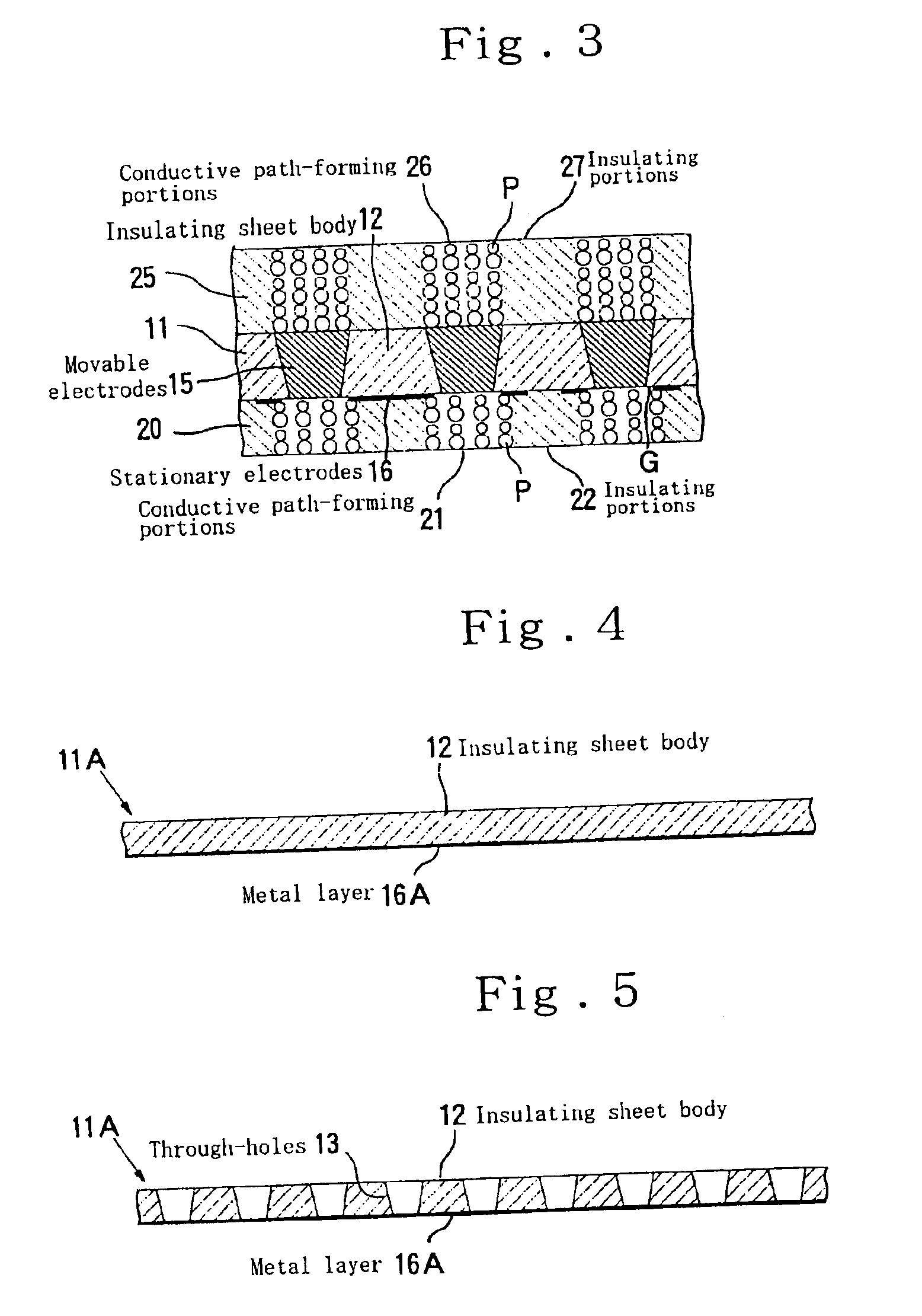
[0194]Composite electrode sheet: Material of insulating sheet body; polyimide, Thickness of insulating sheet body; 0.05 mm, Shape of through-holes; truncated cone, Diameter of opening on the front side; 0.08 mm, Diameter of opening on the back side; 0.12 mm, Material of movable electrodes; nickel, Material of stationary electrodes; copper, The number of openings of through-holes surrounded by one stationary electrode; 1 in the minimum and 40 in the maximum.

[0195]Front-side anisotropically conductive elastomer layer: Material of elastomer; silicon...

referential example 1

[0211]An electric resistance meter, “TR6143” (manufactured by ADVANTEST CORP.) was used to measure an electric resistance between the one-side-electrode to be inspected and the other-side-electrode to be inspected in the circuit board to be inspected by the four probe method of the resistance measurement using probe pins, thereby finding an error range thereof. The result is shown in Table 1.

referential example 2

[0212]The same tester as that used in Example 1 was used to measure an electric resistance between the one-side-electrode to be inspected and the other-side-electrode to be inspected in the circuit board to be inspected by the two probe method of the resistance measurement, thereby finding an error range thereof. The result is shown in Table 1.

[0213]

TABLE 1Error range ofmeasurement of anelectric resistanceExample 1±10mΩComparative Example 1±100mΩReferential Example 1±10mΩReferential Example 2±20Ω

[0214]As apparent from the results shown in Table 1, according to the electric resistance-measuring apparatus according to Example 1, electric resistance can be measured in a small error range (±10 mΩ) equivalent to the electric resistance value measured by the four probe method of the resistance measurement using probe pins, and sufficiently high precision is achieved from the viewpoint of practical use.

[0215]On the other hand, according to the electric resistance-measuring apparatus accord...


PUM


Abstract

Disclosed herein are a connector for measurement of electric resistance, by which an electric resistance-measuring apparatus capable of surely performing expected measurement of electric resistance with high precision even to a circuit board having small-sized, protruding electrodes to be inspected, a scatter of projected heights of said electrodes being great, and easy to produce can be constructed, and electric resistance-measuring apparatus using this connector and method of measurement.
The connector has a composite electrode sheet having an insulating sheet body in which through-holes have been formed corresponding to electrodes to be inspected, movable electrodes supported movably in a thickness-wise direction within the through-holes, and stationary electrodes each formed in the vicinity of openings of the through-holes on a front surface of the insulating sheet body in a state coming into no contact with the movable electrodes, front-side and back-side anisotropically conductive elastomer layers respectively laminated on the front surface and back surface of the composite electrode sheet, and an external leading terminal electrically connected to the stationary electrodes. The movable and stationary electrodes are electrically connected at the same time to corresponding electrodes to be inspected through the front-side anisotropically conductive elastomer layer.

Description

TECHNICAL FIELD[0001]The present invention relates to a connector for measurement of electric resistance, and electric resistance-measuring apparatus for circuit boards and method of measurement.BACKGROUND ART[0002]In recent years, with the request for speeding-up of signal transmission in electronic parts, there has been a demand for circuit boards low in electric resistance of wiring between electrodes for fabricating LSI packages such as BGA and CSP. Therefore, it is extremely important to measure the electric resistance of wiring between electrodes of such a circuit board with high precision in electrical inspection of the circuit board.[0003]In the measurement of an electric resistance of a circuit board, there have heretofore been adopted, for example, means in which probes PA and PD for current supply and probes PB and PC for voltage measurement are pressed against and brought into contact with respective 2 electrodes 91 and 92 to be inspected, which have been electrically co...

Claims


Application Information

Patent Timeline
IPC IPC(8): G01R1/067G01R1/073G01R1/04G01R1/02G01R27/02H01R11/01H05K3/00
CPCG01R1/07328G01R1/07371G01R1/0416G01R1/06755H01R2201/20G01R1/07307G01R27/02
Inventor KIMURA, KIYOSHI
Owner ISC CO LTD
Why Eureka
Try Eureka