Arrangement for reducing transmitted jitter

a technology of jitter reduction and communication system, applied in pulse position modulation, pulse technique, error detection/prevention using signal quality detector, etc., can solve the problems of difficult implementation of acquired tic time, inherently noisy telephone lines, and twisted pair telephone lines suffering from turn-on transients. , to achieve the effect of reducing jitter in transmit waveform communication system

Inactive Publication Date: 2005-06-14
ADVANCED MICRO DEVICES INC
View PDF6 Cites 14 Cited by
  • Summary
  • Abstract
  • Description
  • Claims
  • Application Information

AI Technical Summary

Benefits of technology

[0011]There is a need for an arrangement that minimizes jitter in transmit waveform communications systems that use a single transmit clock, separate from a specified transmit clock.
[0013]These and other needs are attained by the present invention, where a system such as a pulse transmitter includes a phase correction module configured for detecting a phase error between a transmit clock and a prescribed clock specification at a transmit clock instance. The transmit clock instance represents an instance in time in which the pulse transmitter is to transmit data according to the prescribed clock specification. The pulse transmitter also includes pulse shape tables, each configured for outputting a corresponding waveform sample set of a prescribed waveform relative to a corresponding phase offset. Hence, the pulse transmitter is able to compensate for phase differences between the transmit clock utilized by the pulse transmitter and the prescribed clock specification, by outputting a selected waveform sample set that has a corresponding phase offset that compensates for the detected phase error, optimizing the performance of pulse position modulation communications systems that are adversely affected by transmit jitter.
[0014]One aspect of the present invention provides a method in a transmission system configured for outputting a set of waveform samples starting at a transmission time instant according to a transmit clock. The method includes determining a phase error between the transmit clock and a prescribed transmit clock relative to the transmission time instant. The method also includes outputting a selected waveform sample set based on the determined phase error, the waveform sample set having samples of a prescribed waveform relative to a corresponding phase offset, the phase offset of the selected waveform sample set correcting for the determined phase error. Determination of the phase error between the transmit clock and the prescribed transmit clock relative to the transmission time instant enables the transmission system to compensate for the detected phase error, improving the transmission performance of the transmitted waveform to minimize jitter. Moreover, the selection of a waveform sample set having samples of a prescribed waveform relative to a corresponding phase offset enables the precise correction of the determined phase error with minimal complexity.

Problems solved by technology

However, telephone lines are inherently noisy due to spurious noise caused by electrical devices in the home, for example dimmer switches, transformers of home appliances, etc.
In addition, the twisted pair telephone lines suffer from turn-on transients due to on-hook and off-hook and noise pulses from the standard POTS telephones, and electrical systems such as heating and air-conditioning systems, etc.
An additional problem in implementing home networks according to the HomePNA specification 2.0 is that the HomePNA specification specifies pulse transmission times relative to a prescribed multiple of reference clock cycles.
Although the TIC time can be readily generated in a HomePNA transmitter using a divide by seven counter driven by a 60 MHz clock, implementation of the acquired TIC time becomes more difficult if a 60 MHz clock is not readily available, or if a designer prefers not to use a 60 MHz oscillator.
In such case, the use of both a 32 MHz based oscillator and a 60 MHz based oscillator may undesirably result in an expensive transceiver.
Attempts to utilize a 32 MHz clock for generation of the {fraction (7 / 60)} MHz TIC times, however, results in jitter due to the phase differences between the specified transmit clock (e.g., {fraction (7 / 60)} MHz) and the actual transmit clock (e.g., 32 MHz).
Hence, the use of an alternative transmit clock may introduce jitter that adversely affects the required low error data rate transmission.

Method used


Image

  • Arrangement for reducing transmitted jitter
  • Arrangement for reducing transmitted jitter
  • Arrangement for reducing transmitted jitter

Examples


Embodiment Construction

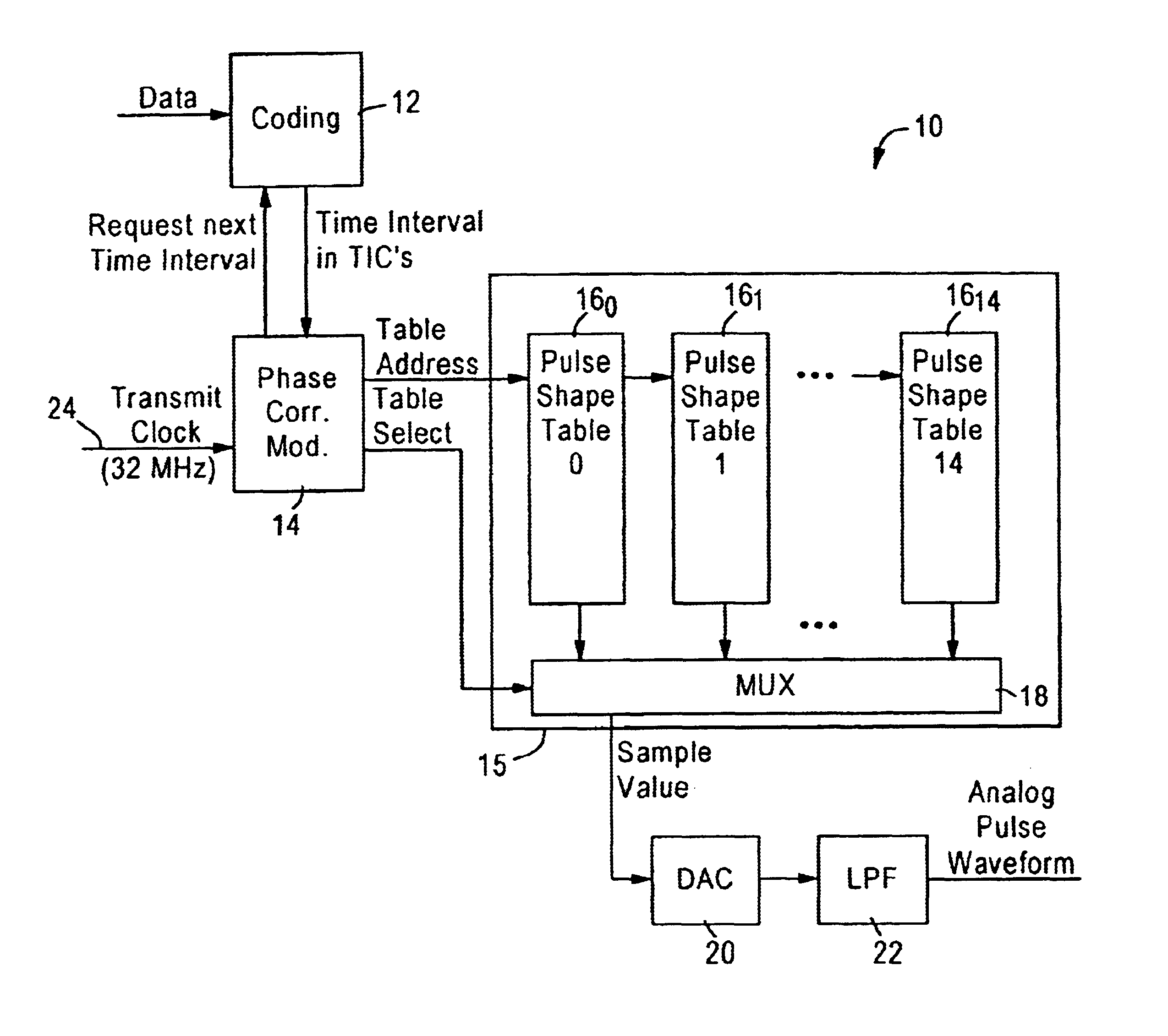
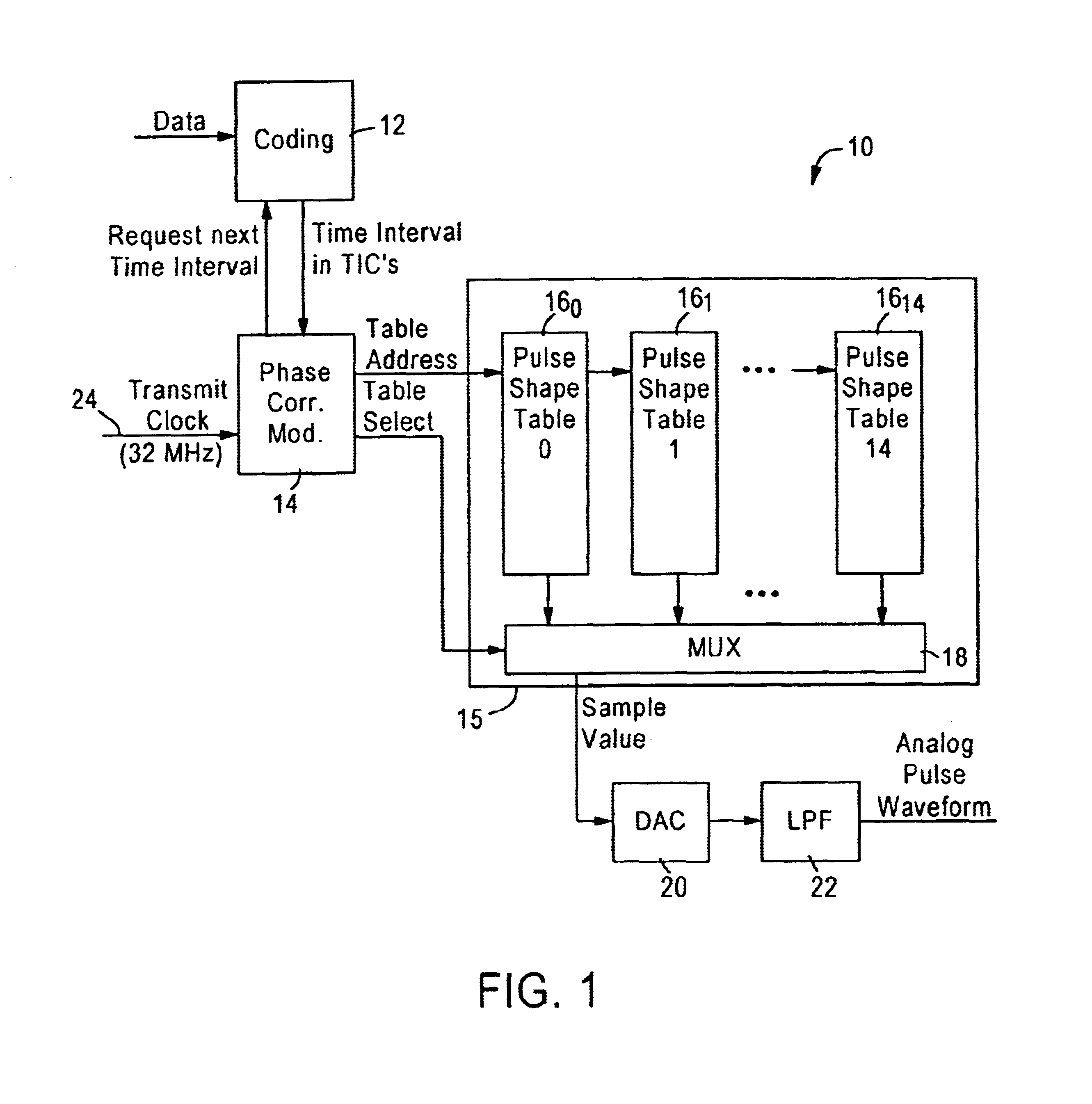
[0025]FIG. 1 is a block diagram illustrating a pulse position modulation communications system 10 configured for outputting an analog pulse waveform at selected transmission time instances according to an embodiment of the present invention. The pulse position modulation communications system 10 may be implemented, for example, in a home PNA physical layer transmitter configured for generating analog home PNA pulses on the boundaries of TIC times that are defined based on a specified transit clock having a normalized period of {fraction (7 / 60)}. In particular, the pulse position modulation communications system 10 includes a coding block 12 configured for generating time interval values, representing respective data values, as unit multiples of a 166.667 ns TIC time.

[0026]The system 10 also includes a phase correction module 14, and a pulse shape table circuit 15. The pulse shape table circuit 15 includes pulse shape tables 16 and a multiplexer 18. The multiplexer 18 is configured f...


PUM


Abstract

A pulse transmitter includes a phase correction module configured for detecting a phase error between a transmit clock and a prescribed clock specification at a transmit clock instance. The transmit clock instance represents an instance in time in which the pulse transmitter is to transmit data according to the prescribed clock specification. The pulse transmitter also includes pulse shape tables, each configured for outputting a corresponding waveform sample set of a prescribed waveform relative to a corresponding phase offset. Hence, the pulse transmitter is able to compensate for phase differences between the transmit clock utilized by the pulse transmitter and the prescribed clock specification, by outputting a selected waveform sample set that has a corresponding phase offset that compensates for the detected phase error, optimizing the performance of pulse position modulation communications systems that are adversely affected by transmit jitter.

Description

[0001]This application claims priority from Provisional Application No. 60 / 218,571, filed Jul. 13, 2000.BACKGROUND OF THE INVENTION[0002]1. Field of the Invention[0003]The present invention relates to pulse position modulation communications systems, for example home networking physical layer transceivers.[0004]2. Background Art[0005]Local area networks use a network cable or other media to link stations on the network. Each local area network architecture uses a media access control (MAC) enabling network interface cards at each station to share access to the media.[0006]Conventional local area network architectures use a media access controller operating according to half-duplex or full duplex Ethernet (ANSI / IEEE standard 802.3) protocol using a prescribed network medium, such as 10BaseT. Newer operating systems require that a network station be able to detect the presence of the network. In an Ethernet 10BaseT environment, the network is detected by the transmission of a link pul...

Claims


Application Information

Patent Timeline
Patent Type & Authority Patents(United States)
IPC IPC(8): H03K7/04H03K7/00H04L1/20
CPCH04L1/205
Inventor NAYLER, COLIN D.
Owner ADVANCED MICRO DEVICES INC
Why Eureka
Try Eureka