
Apparatus and method for electronic tire testing

a technology of electronic tires and apparatus, applied in vehicle testing, structural/machine measurement, ways, etc., can solve the problems of inability to reliably detect certain flaws, inability to detect flaws that involve defects too fine or too obscure to be seen visually, and inadvertently overlooked, so as to reduce equipment costs correspondingly, increase efficiency, and save time in the testing process

Inactive Publication Date: 2005-06-21
GUSTAFSON DALE ALAN
View PDF61 Cites 35 Cited by
  • Summary
  • Abstract
  • Description
  • Claims
  • Application Information

AI Technical Summary

Benefits of technology

[0012]With the unique positioning aspects of the electrodes described above, the need to spread the beads of a tire carcass for insertion of the test head is eliminated, thus greatly increasing efficiency and saving time in the testing process.
[0013]Also, the positioning of both electrodes inside the tire with the high-voltage electrode inductively coupled with a steel belt in the tire, eliminates the need for a separate grounding element that must be positioned on the outside of the tire in close proximity to a high voltage head on the inside of the tire. Equipment costs are correspondingly reduced. In addition, the decreased impedance resulting from only the inner liner portion of the tire being disposed between the steel belt and each electrode enables a lower potential to be used for the high voltage head, thus saving costs, while also providing the same or improved detection performance for smaller flaws. Moreover, since both electrodes are positioned inside the tire, no contact with the outside tread portion of the tire is required, thereby reducing the possibility of contamination if the tread portion of the tire has been buffed.

Problems solved by technology

Visual inspection, however, while useful for detecting gross flaws in tire carcasses being evaluated for possible retreading, is not suited for reliably detecting certain flaws.
In particular, flaws that involve a defect too fine or too obscure to detect visually may be inadvertently overlooked and retreaded to produce a defective retreaded tire.
Special equipment may be required for spreading the beads of the tire, presenting an additional cost and requiring additional time for testing each tire.
Flexibility and ease of use of the equipment is limited, since the elements must be carefully maintained in position on the inside and outside of the tire.
Also, relatively high electrical potentials are used in prior devices to overcome the impedance presented by such an arrangement, resulting in costly equipment components.
Even with such higher potentials, smaller defects may sometimes go undetected.

Method used


Image

  • Apparatus and method for electronic tire testing
  • Apparatus and method for electronic tire testing
  • Apparatus and method for electronic tire testing

Examples


Embodiment Construction

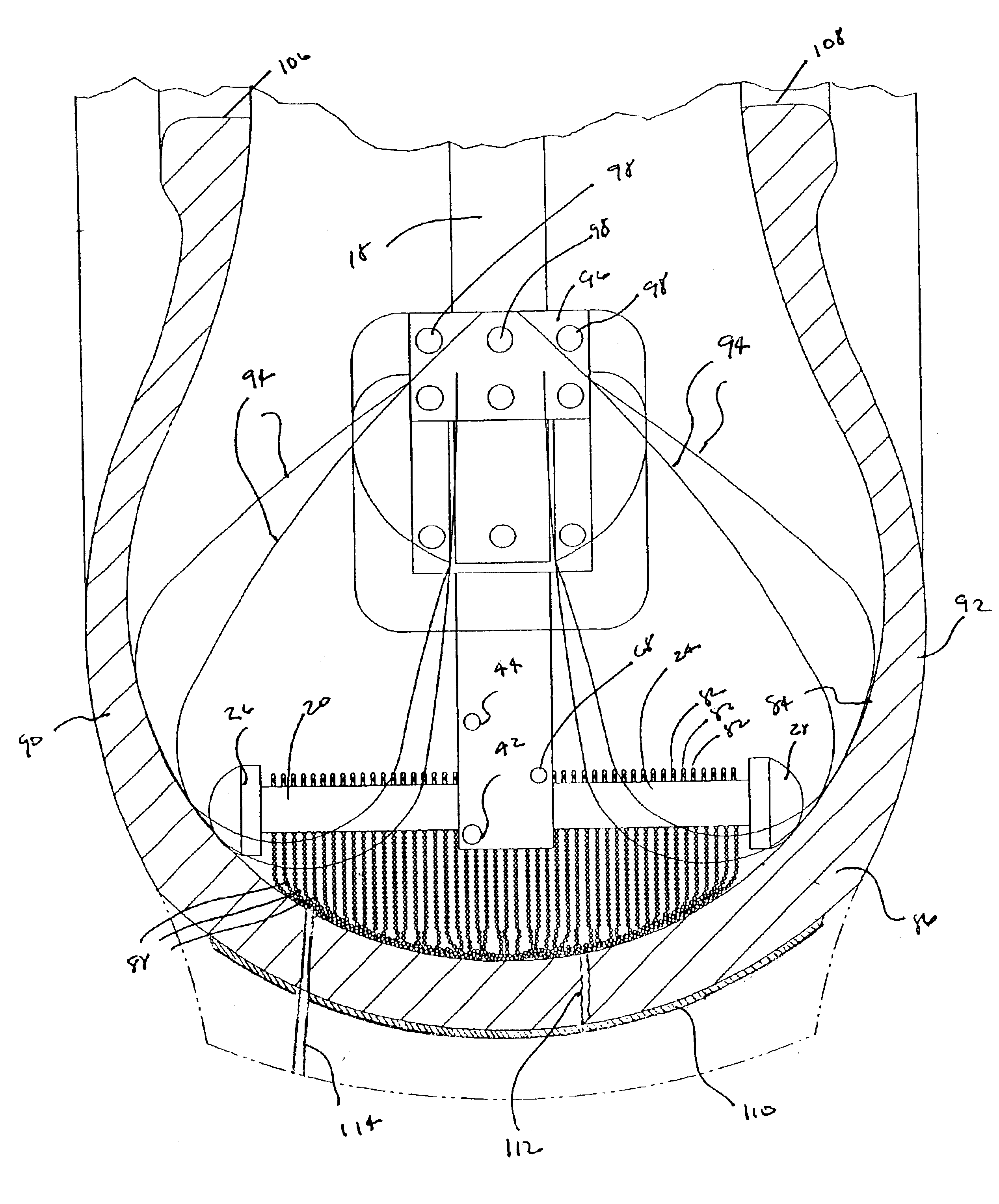
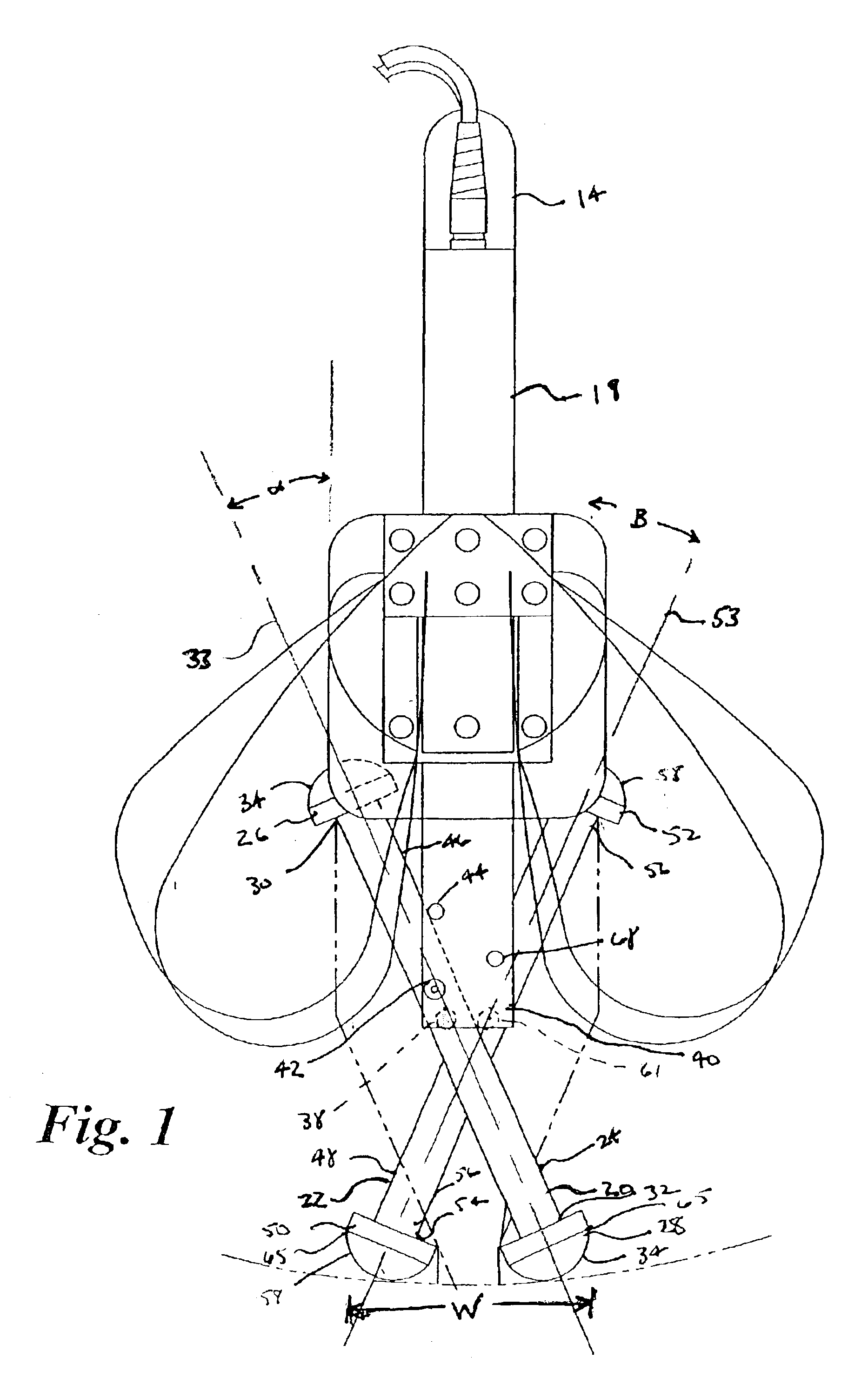
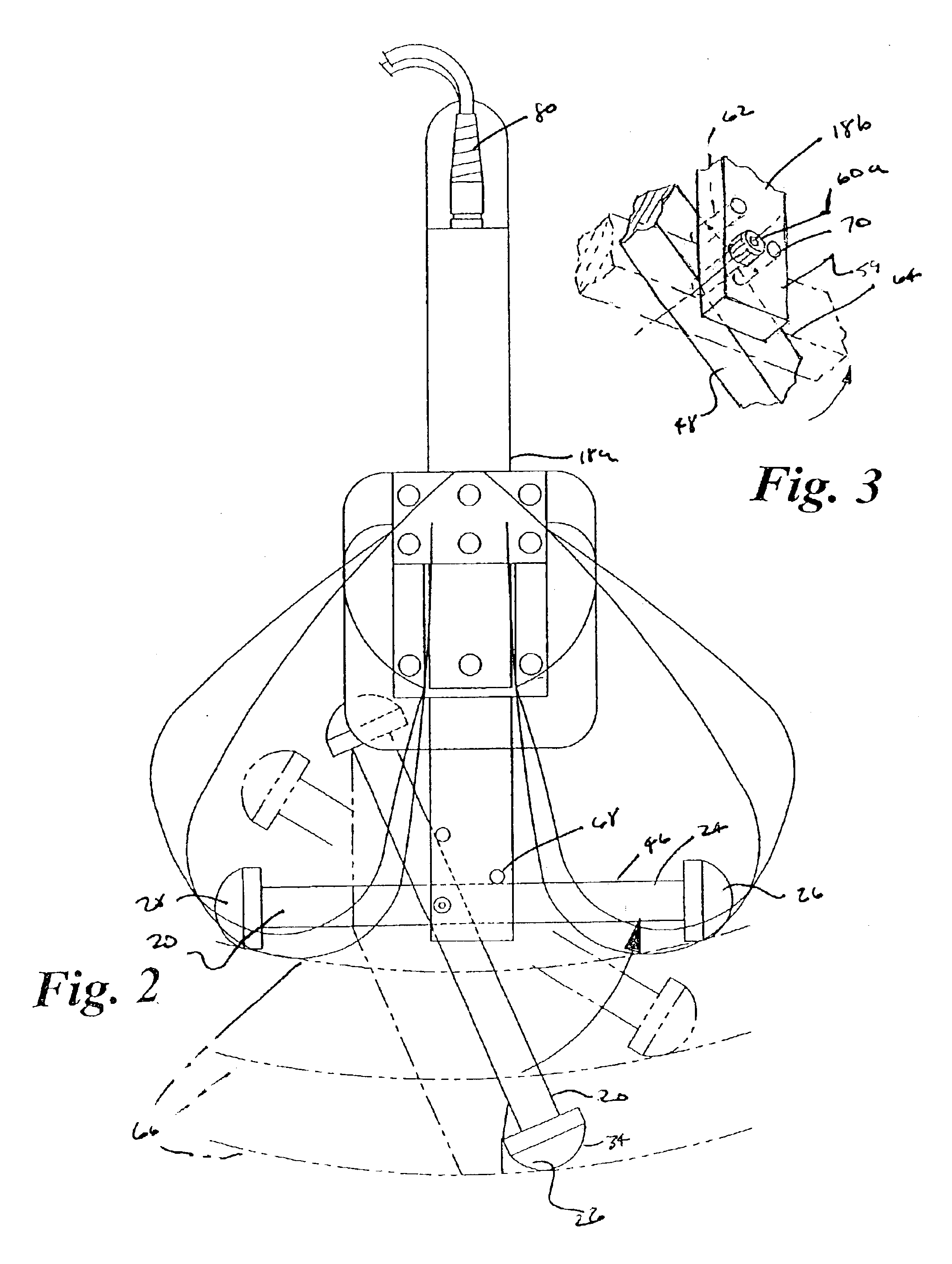
[0025]Tire testing apparatus 10 generally includes high-potential electrical power source 12 and testing head 14. High potential electrical power source 12 may be a voltage generator used to generate a high voltage, such that the electric arcs produced upon detection of a flaw are visible to a human eye. In one embodiment the high potential electrical power source 12 may produce a voltage of approximately 40,000 volts. In other embodiments, voltages of from 20,000 to 60,000 volts may be used. Any voltage, including those within and outside the range of the voltages listed herein, may be used within the scope of the tire test apparatus 10 of the invention. The high potential electrical power source 12 shown in FIG. 7 may be contained within a box with wheels 16 such that it may be easily moved in a tire retread shop to different areas. U.S. Pat. Nos. 4,520,307 and 6,304,090 each disclose high potential electrical power sources 12 that may be suitable for use with the invention. Other...


PUM


Abstract

A testing head for a high voltage non-destructive tire testing apparatus that is positionable inside the carcass of a tire to be tested without spreading the beads of the tire. The testing head includes a horseshoe shaped body portion with a pair of depending legs. An electrode is operably coupled at the end of each leg. One of the electrodes is attached to a high-voltage power source and the other electrode is attached to electrical ground. Each electrode may be attached off-center from the center of gravity of the electrode so that the electrode is positioned at an angle with the leg to which it is attached when the testing head is suspended by the body portion and the electrodes are not in contact with a tire or other surface. When the electrodes are brought into contact with the inner surface of the tire carcass, the electrodes rotate into a testing orientation wherein each electrode is substantially perpendicular with the leg to which it is attached. The tire carcass is rotated, so that a portion of the electrodes slide over the inner surface of the tire. The high voltage electrode inductively couples with steel belts in the tire carcass, thereby causing the steel belts to have an elevated electrical potential relative to ground potential. When either electrode passes over a flaw in the tire, an arc passes through the flaw between the steel belt and the electrode closest to the flaw.

Description

RELATED APPLICATIONS[0001]This application claims benefit under 35 U.S.C. 119(e) of U.S. Provisional Patent Application Ser. No. 60 / 369,918 filed Apr. 4, 2002, and U.S. Provisional Patent Application Ser. No. 60 / 370,176 filed Apr. 5, 2002, both of which are hereby incorporated fully herein by reference.FIELD OF THE INVENTION[0002]The present invention relates to non-destructive testing of vehicular tires, and specifically to apparatus and methods for non-destructive testing of vehicular tires with high-potential electricity.BACKGROUND OF THE INVENTION[0003]It is common to retread worn vehicular tires so that the tires may be reused. Typically, a tire carcass is inspected prior to applying a new tread portion in order to detect any flaws in the carcass, such as a defect in the inner liner, that would make the carcass unsuitable for retreading.[0004]Visual inspection of a tire carcass to detect flaws has been known for many years, and is typically employed as one part of the inspectio...

Claims


Application Information

Patent Timeline
Patent Type & Authority Patents(United States)
IPC IPC(8): G01M17/02
CPCG01M17/02
Inventor WEISS, ARNOLD A.
Owner GUSTAFSON DALE ALAN
Learn More