Methods of supplying energy to an energy bus in a hybrid electric vehicle, and apparatuses, media and signals for the same

a hybrid electric vehicle and energy bus technology, applied in the field of vehicles, can solve the problems of inability to draw electrical energy from the energy bus and convert it into another form, regenerative braking typically produces a significant amount of surplus electrical energy, and the ability of the energy storage system to safely receive and store energy is typically limited

Inactive Publication Date: 2005-06-21
GE HYBRID TECH
View PDF38 Cites 122 Cited by
  • Summary
  • Abstract
  • Description
  • Claims
  • Application Information

AI Technical Summary

Benefits of technology

[0017]Controlling preferably includes reducing the power supplied by the energy generating device to the energy bus. If so, the method may further include increasing power supplied by the regenerative braking system of the vehicle to the energy bus, while reducing the power supplied by the energy generating device to the energy bus.
[0018]Thus, in such an embodiment, regenerative braking energy is effectively favored over energy supplied by the energy generating device, thereby improving the efficiency of the vehicle by increasing the amount of energy recovered from the vehicle's kinetic energy while decreasing fuel consumption.
[0025]The method may further include setting a friction braking torque of a friction braking system of the vehicle. This may include setting the friction braking torque equal to a difference between the present desired regenerative braking torque and the total desired braking torque. Thus, friction brakes may be used to complement the regenerative braking system if required, in order to provide adequate total braking torque to provide a consistent and predictable brake feel.
[0026]Controlling preferably includes controlling energy contributions onto the energy bus from the energy generating device and from a regenerative braking system of the vehicle respectively, to prevent the contributions from exceeding a desired total energy contribution.
[0042]In accordance with another aspect of the invention, there is provided a method of supplying energy to an energy bus in a hybrid electric vehicle. The method includes controlling energy contributions onto the energy bus from an energy generating device and from a regenerative braking system respectively, to prevent the contributions from exceeding a desired total energy contribution.
[0043]Controlling preferably includes reducing power supplied by the energy generating device to the energy bus.

Problems solved by technology

The auxiliary power unit typically converts another form of energy into electrical energy which it supplies to the energy bus, but is usually not capable of drawing electrical energy from the energy bus and converting it into another form for storage.
Therefore, regenerative braking typically produces a significant amount of surplus electrical energy that can be stored by the energy storage system.
However, the ability of the energy storage system to safely receive and store energy is typically limited by a number of factors, such as its state of charge, its temperature, its age, and its previous operating conditions, for example.
Exceeding the charge acceptance limit of the energy storage system may lead to over-voltage conditions, potentially damaging the energy storage system, and also potentially damaging other electronic components connected to the energy bus.
Therefore, to the extent that the auxiliary power unit and the regenerative braking system may produce surplus electrical energy (i.e., energy in excess of the current electrical needs of the vehicle), if such surplus electrical energy exceeds the amount of energy the energy storage system can safely store, the energy storage system and other electric and / or electronic components of the vehicle may be damaged.
It is noted that reducing regenerative braking output in favor of the generator output disadvantageously reduces vehicle efficiency.
More significantly, existing systems tend to be reactionary in nature, and often cannot prevent short but damaging voltage spikes from occurring.
If the user then brakes suddenly, the traction motors suddenly switch from operating as a large energy drain to operating as a generator, supplying a large supply of electrical energy to the energy bus, while at the same time, the auxiliary power unit will still initially be operating at or near full power, not having had sufficient time to reduce its output.
The resulting surplus electrical energy supplied to the energy bus by the traction motors and the auxiliary power unit typically largely exceeds the charge acceptance of the energy storage system, and the resulting over-voltage condition on the energy bus not only has a detrimental effect on the service life of the energy storage system, but is also potentially damaging to other electronic and / or electrical devices connected to the energy bus.
A conventional reactionary system may detect and respond to the over-voltage condition, but typically not until after such potentially damaging voltage spikes have occurred.

Method used


Image

  • Methods of supplying energy to an energy bus in a hybrid electric vehicle, and apparatuses, media and signals for the same
  • Methods of supplying energy to an energy bus in a hybrid electric vehicle, and apparatuses, media and signals for the same
  • Methods of supplying energy to an energy bus in a hybrid electric vehicle, and apparatuses, media and signals for the same

Examples


first embodiment

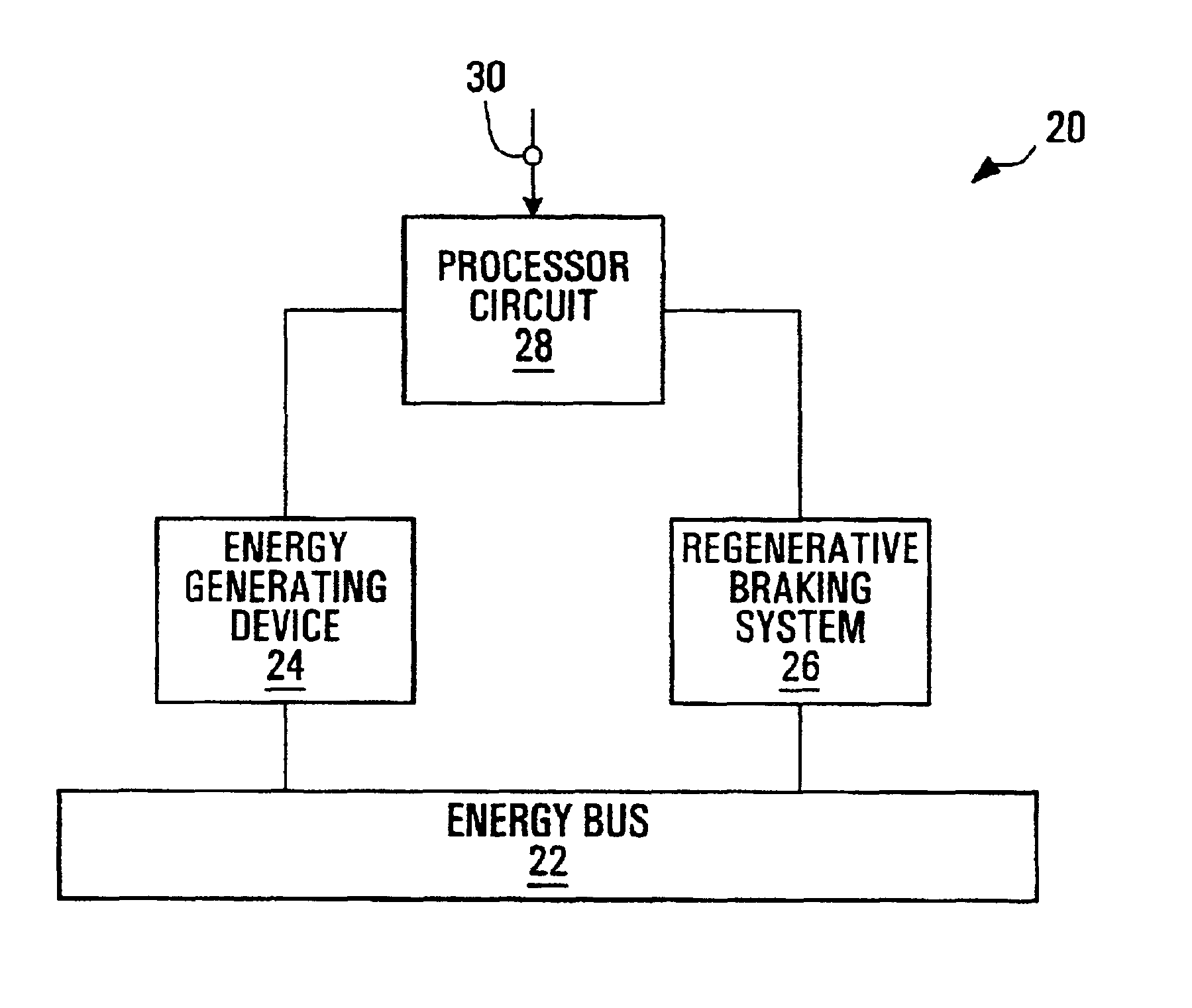
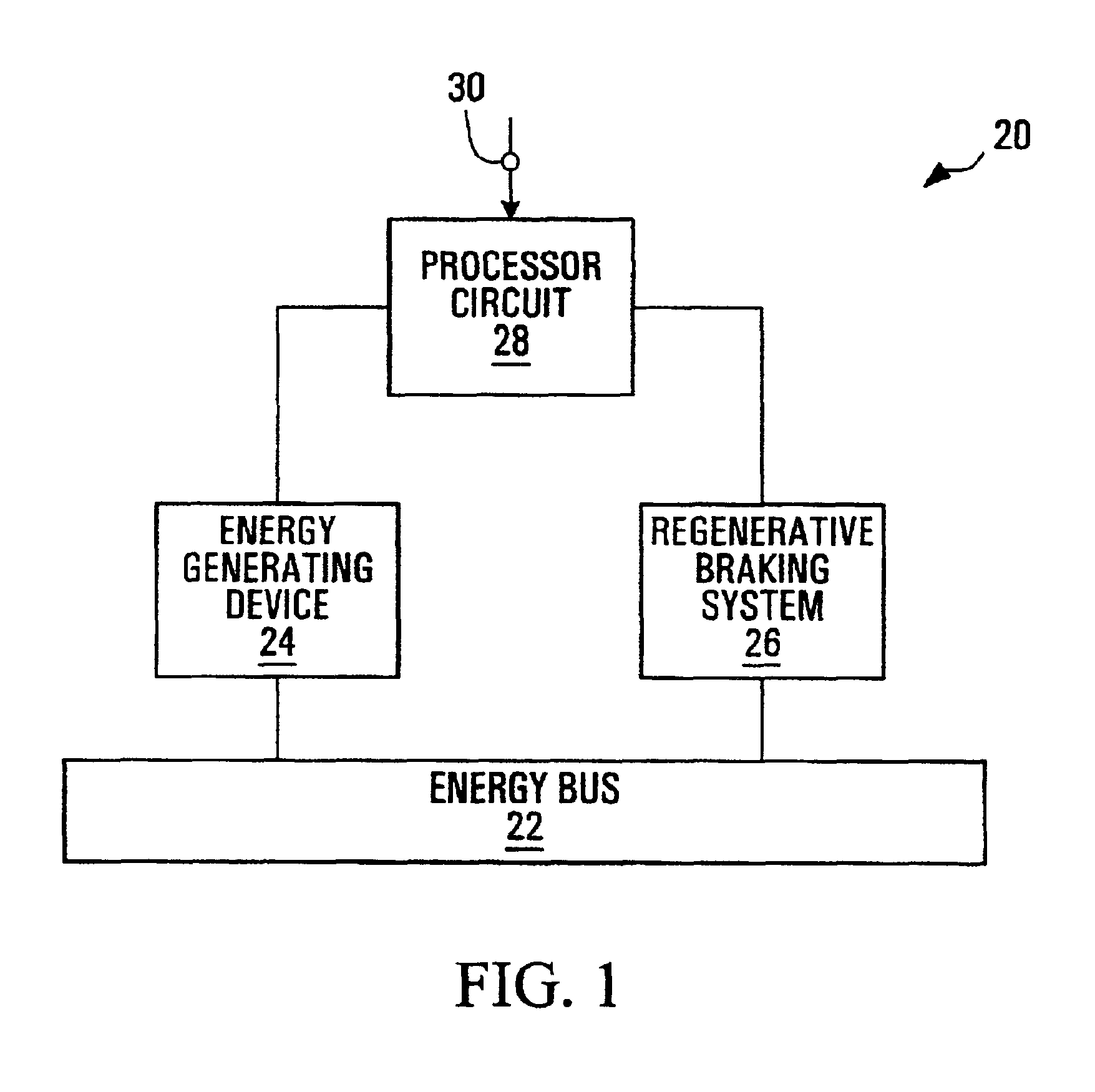
[0063]Referring to FIG. 1, an apparatus according to the invention is shown generally at 20. In this embodiment, the apparatus is used for supplying energy to an energy bus 22 in communication with an energy generating device 24 and with a regenerative braking system 26 in a hybrid electric vehicle (not shown). The apparatus 20 includes a processor circuit 28, configured to control power supplied by the energy generating device 24 to the energy bus 22, in response to a braking signal 30 indicative of user brake actuation.

[0064]In this embodiment, the processor circuit 28 is configured to control energy contributions onto the energy bus 22 from the energy generating device 24 and from the regenerative braking system 26 respectively, to prevent the contributions from exceeding a desired total energy contribution.

second embodiment

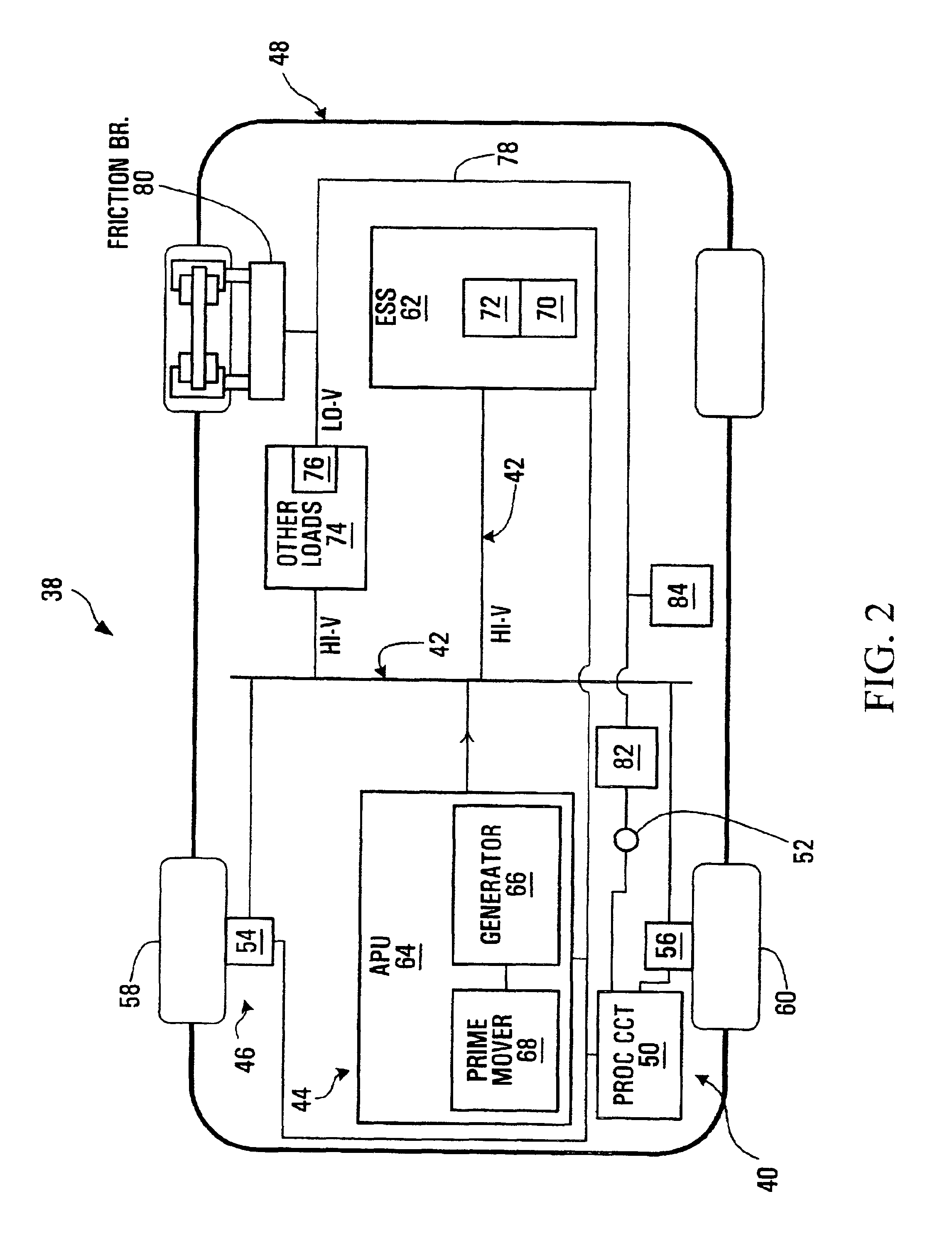
[0065]Referring to FIG. 2, a system according to the invention is shown generally at 38. In this embodiment, the system 38 includes an apparatus 40 for supplying energy to an energy bus 42 in communication with an energy generating device shown generally at 44 and with a regenerative braking system shown generally at 46, in a hybrid electric vehicle 48. In this embodiment, the apparatus 40 includes a processor circuit 50 configured to control power supplied by the energy generating device 44 to the energy bus 42, in response to a braking signal 52 indicative of user brake actuation. In this embodiment, the processor circuit 50 is also configured to control energy contributions onto the energy bus 42 from the energy generating device 44 and from the regenerative braking system 46 respectively, to prevent the contributions from exceeding a desired total energy contribution.

[0066]In this embodiment, the hybrid electric vehicle 48 includes a series hybrid electric vehicle. The regenerat...


PUM


Abstract

Methods, apparatuses, media and signals for supplying energy to an energy bus in communication with an energy generating device and with a regenerative braking system in a hybrid electric vehicle are disclosed. One such method includes controlling power supplied by the energy generating device to the energy bus, in response to a braking signal indicative of user brake actuation. Another such method involves controlling energy contributions onto the energy bus from the energy generating device and from the regenerative braking system respectively, to prevent the contributions from exceeding a desired total energy contribution. The energy generating device may include an auxiliary power unit, such as fuel cell, or a generator coupled to a prime mover such as an internal combustion engine, for example.

Description

FIELD OF THE INVENTION[0001]The present Invention relates to vehicles, and more particularly to methods, apparatuses, media and signals for supplying energy to an energy bus in a hybrid electric vehicle.BACKGROUND OF THE INVENTION[0002]An electric or hybrid electric vehicle typically employs electric traction motors connected to drive wheels of the vehicle. The traction motors typically receive electrical energy from an energy bus of the vehicle, in response to which the motors apply a torque to the drive wheels, thereby causing the vehicle to accelerate.[0003]In a “series” hybrid electric vehicle, there are typically two available power sources to supply energy to the traction motors to drive the vehicle: an auxiliary power unit or other energy generating device, and an energy storage system.[0004]The auxiliary power unit typically converts another form of energy into electrical energy which it supplies to the energy bus, but is usually not capable of drawing electrical energy from...

Claims


Application Information

Patent Timeline
Patent Type & Authority Patents(United States)
IPC IPC(8): B60L11/12B60L11/02B60L15/20B60K6/04B60K6/00B60K6/28B60K6/32B60K6/46B60L7/10B60L50/15B60W10/26
CPCB60K6/28B60K6/32B60K6/46B60L11/123B60L15/2045B60W10/26Y10S903/907Y02T10/7077Y02T10/7283Y02T90/16Y02T90/34Y10S903/908Y02T10/6217B60L50/61Y02T10/62Y02T10/64Y02T10/72Y02T90/40Y02T10/70B60L7/10B60L15/20B60W20/00Y02T10/7072
Inventor BOUCHON, NICOLAS LOUIS
Owner GE HYBRID TECH
Why Eureka
Try Eureka