Statistic parameterized control loop for compensating power and extinction ratio of a laser diode

a technology of applied in the field of optical transceivers, can solve the problems of reducing the reliability of a digital communication system, increasing the bit error rate (ber) and clock jitter at the receiver end, and increasing the transmission power, so as to minimize the fluctuation of laser output power and extinction ratio.

Inactive Publication Date: 2005-06-21
CENTILLIUM COMM
View PDF3 Cites 38 Cited by
  • Summary
  • Abstract
  • Description
  • Claims
  • Application Information

AI Technical Summary

Benefits of technology

[0014]In one embodiment, the laser diode drive current includes components of a bias current ib and a modulation current im, and an automatic power control module adjusts the bias current ib and modulation current im simultaneously based on the second order statistics. One advantage of the simultaneous adjustment is that it minimizes the fluctuation of the laser output power and the extinction ratio during the adjustment of ib and im. This is an improvement over conventional techniques which adjust the average power and extinction ratio in a sequential fashion via a state machine or by setting a separate

Problems solved by technology

These variations in the average optical power and the extinction ratio P1/P0 during data transmission can reduce the reliability of a digital communication system.
For example, such variations can increase the bit error rate (BER) and clock jitter at the receiver end.
Also, if the original transmission is set at P1′ and P′0, and the laser temperature is decreased, the transmission power will increase, thereby overdriving the laser diode, which can damage the laser diode, as well as increasing the BER at the receiver.
Especially for higher temperatures, the method described above often yield a higher extinction ratio then the desired level because the power-current (P-I) characteristics of a practical laser diode are nonlinear.
This a

Method used


Image

  • Statistic parameterized control loop for compensating power and extinction ratio of a laser diode
  • Statistic parameterized control loop for compensating power and extinction ratio of a laser diode
  • Statistic parameterized control loop for compensating power and extinction ratio of a laser diode

Examples


embodiment 600

[0035]FIG. 6 is a flow diagram illustrating a method 600 for simultaneously adjusting an output power and an extinction ratio of a laser diode based on on a reference average power and a variation from the reference average power in accordance with an embodiment of the present invention. For illustrative purposes only, the method embodiment 600 illustrated in FIG. 6 is discussed in the context of the system embodiment of FIG. 4.

[0036]When the laser diode is powered-on or a recalibration request is received, the laser diode's drive current is calibrated for the desired reference P1 and P0 levels. In one example, these reference P1 and P0 levels can be set according to an average output power and extinction ratio for optimal reception at a receiver (not shown) across a transmission medium. The APC 410 determines 602 the laser diode drive current idd for a reference P1 and a reference P0 level. The APC 410 determines 604 a reference average power and a reference power variance for the ...

embodiment 800

[0059]FIG. 8 is a flow diagram of a method 800 for determining a reference average power Pref and a reference power output variance Vref representative of the reference P1 and P0 levels for the desired extinction ratio P1 / P0 in accordance with an embodiment of the present invention. This method embodiment 800 is typically performed during a parameter estimation phase following the initial calibration phase when the laser diode transmitter 402 is initially powered on.
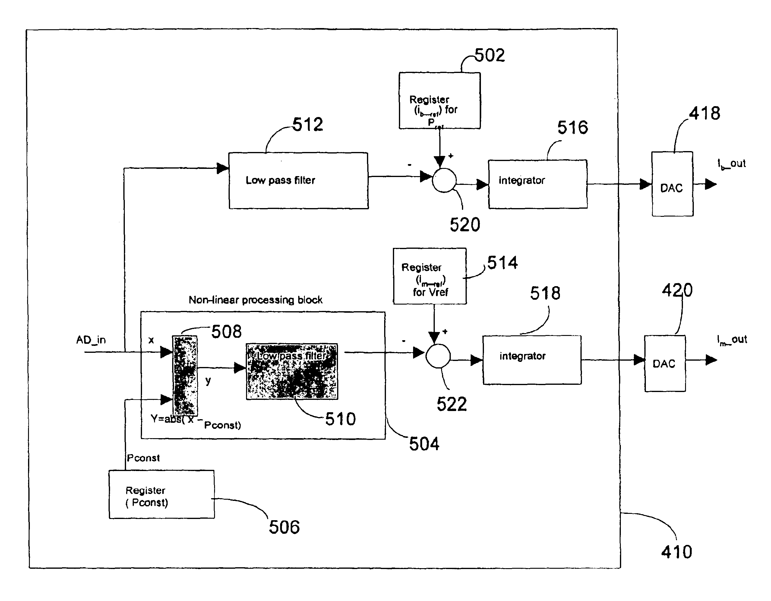
embodiment 400

[0060]In the example context of the system embodiment 400 illustrated in FIG. 4, using the initial values for ib—out and im—out determined in the calibration phase, a random data input (e.g. 424) is provided to the laser diode drive current generator 422 causing the laser diode 402 to produce an optical power swing from corresponding power levels P0 and P1 over a parameter estimation time period Par_T. The values Pref and Vref are then estimated, and used by the APC 410 for adjusting parameters such as the laser diode drive current idd effecting the laser optical power extinction ratio and average power level to maintain the desired level in an extinction ratio and power level compensation phase. Particularly for a laser diode 402 used as a transmitter, the extinction ratio and power level are monitored continuously during normal transmitter operation and parameters are adjusted responsive to the monitored feedback.

[0061]The APC 410 initializes 802 parameters for the power parameter...


PUM


Abstract

An automatic closed loop power control system is described for simultaneously adjusting an output power and an extinction ratio P1/P0 of a laser diode in order to maintain a desired average output power and a desired extinction ratio. The bias current component of a laser diode drive current is adjusted to compensate for changes in the average output power caused by ambient characteristics such as temperature and aging. Simultaneously, a modulation current component of the laser diode drive current is adjusted to maintain an extinction ratio of the laser diode output signal. The bias current and modulation current adjustments are based on the second order statistics of an average output power of the laser diode and a variance in the power output of the laser diode.

Description

CROSS-REFERENCE TO RELATED APPLICATIONS[0001]This application claims priority under 35 U.S.C.§ 119(e) from U.S. provisional patent application 60 / 442,302, having a filing date of Jan. 23, 2003, entitled “Statistic Parameterized Control Loop for Compensating Power and Extinction Ratio of a Laser Diode,” having inventor Cheng Youn Lu, which is hereby incorporated by reference.FIELD OF THE INVENTION[0002]The present invention relates generally to optical transceivers for use in optical communication systems, and more particularly, to compensating the power and extinction ratio of a laser diode.BACKGROUND[0003]Laser diodes are typically used in optical transceivers to convert electric current into optical power for data transmission. The laser diode translates the laser current to optical power values P1 and P0, which represent the binary values “1” and “0”, respectively. Due to temperature changes and / or laser diode aging, the characteristics of a laser diode in operation will change.[...

Claims


Application Information

Patent Timeline
IPC IPC(8): H01S3/13H01S3/30H01S3/10H01S3/00H04BH04B10/155
CPCH04B10/564H04B10/504
Inventor LU, CHENG YOUN
Owner CENTILLIUM COMM
Why Eureka
Try Eureka