FM modulator

a modulator and fm technology, applied in the field of fm modulators, can solve the problems of amplitude increase of inputted signals to the fm, sharp extreme deterioration of distortion characteristics, etc., and achieve the effect of reducing the quality of fm demodulation signals, facilitating the generation of optical frequency-modulated signals, and high quality

Inactive Publication Date: 2005-06-21
PANASONIC CORP
View PDF14 Cites 5 Cited by
  • Summary
  • Abstract
  • Description
  • Claims
  • Application Information

AI Technical Summary

Benefits of technology

[0022]Since a semiconductor laser can easily generate an optical frequency-modulated signal by modulating its injection current, it is suitable for the first and second FM light element. However, when the injection current to the semiconductor laser is subjected to modulation, the outputted light is subjected to modulation in intensity, and when the resultant light is subjected to square-law detection in the optical-electrical converting portion, an optical intensity modulation / direct detection component (IM-DD component) is generated. The IM-DD component is an unwanted signal with respect to the wide-band FM signal, deteriorating the quality of the FM demodulation signal.
[0023]When the first and second FM light sources perform modulating operation by electrical signals whose phases are opposite, the first and second IM-DD components also have an opposite phase relationship with each other. Therefore, in the above fourth aspect, signal power is adjusted at appropriate positions on two propagation routes from the branch portion to the optical-electrical converting portion to equate the magnitudes of the first and second IM-DD components, and these components are canceled / suppressed in the optical-electrical converting portion. It is thus possible to generate a wide-band FM signal with high quality without an unwanted signal.

Problems solved by technology

The spectral line widths of these two light sources are parameters depending on the composition and structure of each light source and cannot be changed greatly by limitations such as use conditions and the like.
However, since the laser light source has a threshold characteristic, when the amplitude of the inputted signal is increased to more than a prescribed degree, a distortion characteristic is extremely deteriorated due to clipping of the signal amplitude and the like.
Furthermore, the outputted signal level of the driving amplifier 602 has a limit (saturated level), and if the outputted signal level is increased over a prescribed level, the distortion characteristic is sharply deteriorated.
Therefore, the amplitude increase of the inputted signal to the FM laser 604 is limited, and it is thus disadvantageously difficult to improve the CNR to more than a prescribed degree.

Method used


Image

  • FM modulator
  • FM modulator
  • FM modulator

Examples


first embodiment

[0045](First Embodiment)

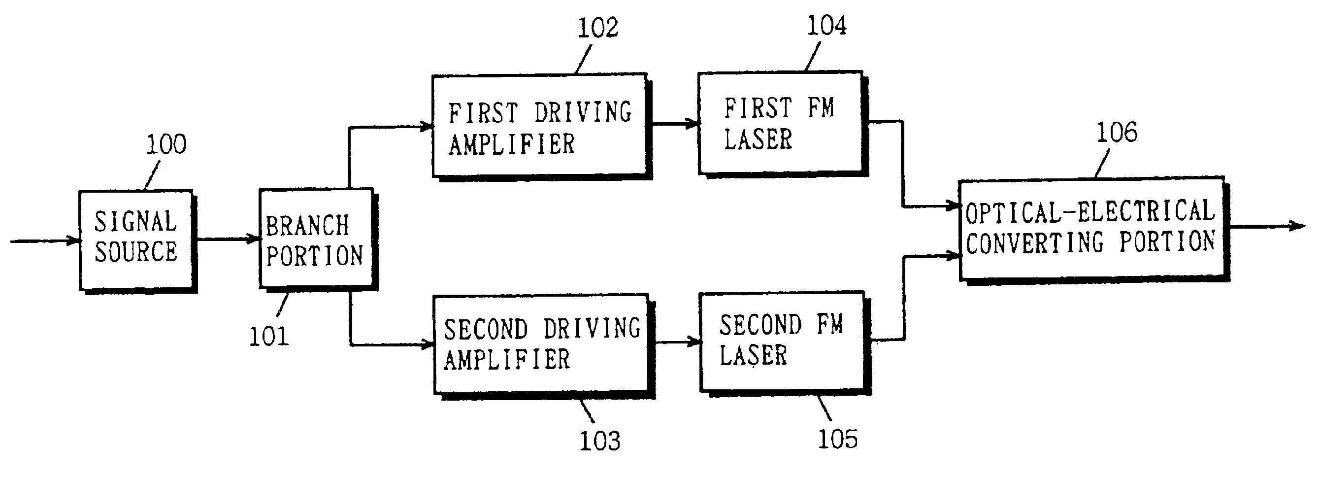
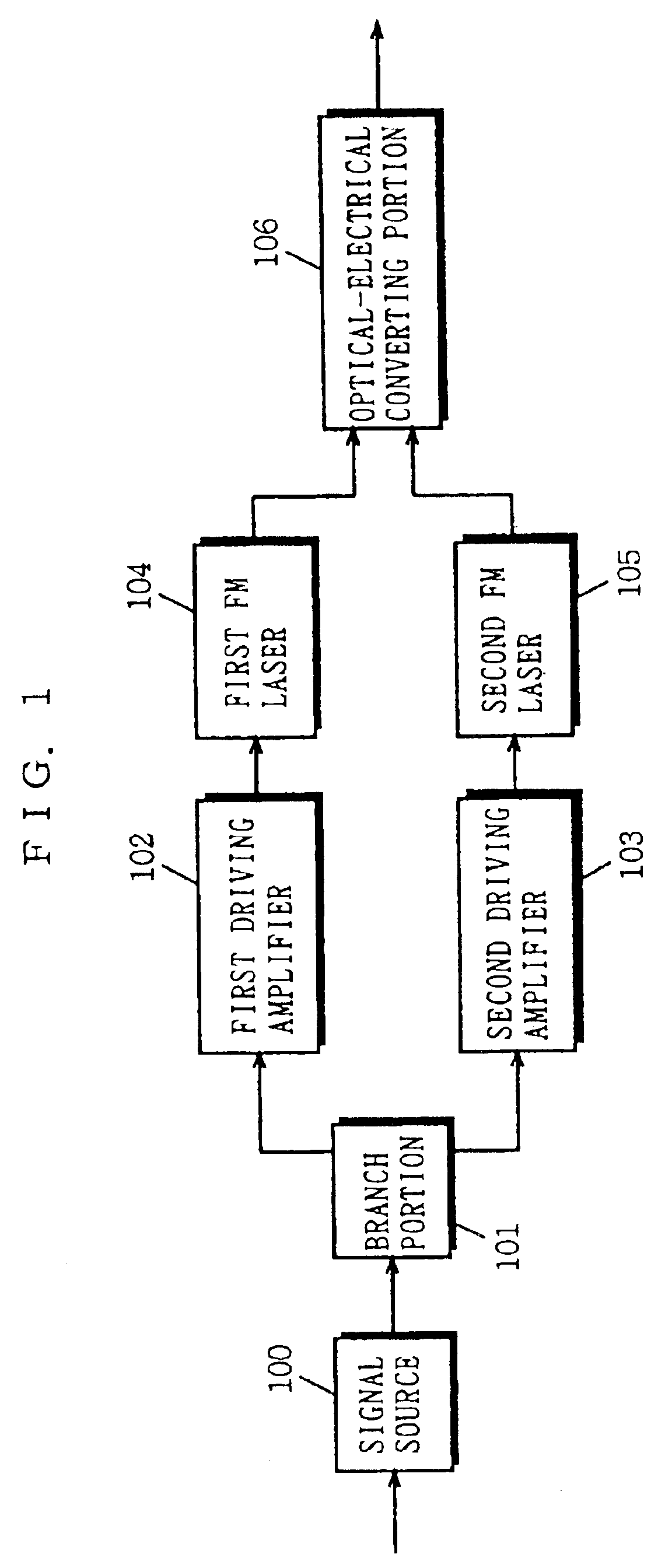
[0046]FIG. 1 is a block diagram showing the structure of an FM modulator according to a first embodiment of the present invention. In FIG. 1, the FM modulator of the present embodiment includes a signal source 100, a branch portion 101, a first frequency modulation laser (hereinafter referred to as a first FM laser) 104, a second frequency modulation laser (hereinafter referred to as a second FM laser) 105, and an optical-electrical converting portion 106. Further, as required, the FM modulator includes first and second driving amplifiers 102 and 103.

[0047]Described next is operation of the embodiment shown in FIG. 1. The signal source 100 outputs an electrical signal which is an original signal for FM modulation. The branch portion 101 branches the electrical signal outputted from the signal source 100 into a phase-uninverted signal (in-phase signal) and a phase-inverted signal (opposite phase signal) and outputs each of these signals. The first and second d...

second embodiment

[0050](Second Embodiment)

[0051]FIG. 3 is a block diagram showing the structure of an FM modulator according to the second embodiment of the present invention. In FIG. 3, the FM modulator of the present embodiment includes, in addition to the structure in FIG. 1, an amplitude adjusting portion 207.

[0052]Described next is operation of the embodiment shown in FIG. 3. Since most part of the structure in the present embodiment is the same as that of the above described first embodiment, only different operation is described below. The amplitude adjusting portion 207 adjusts a signal amplitude level of the in-phase signal outputted from the branch portion 101 to equate frequency deviation of the first and second optical signals. The same effect can be obtained when the amplitude adjusting portion 207 is inserted between the first driving amplifier 102 and the first FM laser 104. Further, according to the characteristic of the semiconductor laser used as the first and second FM lasers 104 ...

third embodiment

[0053](Third Embodiment)

[0054]FIG. 4 is a block diagram showing the structure of an FM modulator according to the third embodiment of the present invention. In FIG. 4, the FM modulator of the present embodiment includes, in addition to the structure in FIG. 1, a delay adjusting portion 308.

[0055]Described next is operation of the embodiment shown in FIG. 4. Since most part of the structure of the present embodiment is the same as that of the above described first embodiment, only different operation is described below. The delay adjusting portion 308 adds appropriate propagation delay to the in-phase signal outputted from the branch portion 101 to equate propagation delay with which the in-phase signal outputted from the branch portion 101 reaches through the first FM laser 104 the optical-electrical converting portion 106 and propagation delay with which the opposite phase signal outputted from the branch portion 101 reaches through the second FM laser 105 the optical-electrical co...


PUM


Abstract

A branch portion 101 branches an inputted electrical signal into an in-phase signal and an opposite phase signal which have an opposite relation as to a phase. A first FM laser 104 converts the in-phase signal into an optical frequency-modulated signal (a first optical signal) having a center wavelength λ1 and then outputs the resultant signal. A second FM laser 105 converts the opposite phase signal into an optical frequency-modulated signal (a second signal) having a center wavelength λ2 and then outputs the resultant signal. The two optical signals are combined and then inputted into an optical-electrical converting portion 106. The optical-electrical converting portion 106 subjects the inputted optical signals to optical heterodyne detection by its square-law detection characteristic, and outputs a beat signal between the two optical signals which is a wide-band FM signal at a frequency corresponding to a wavelength difference Δλ(=|λ1−λ2|) between the first optical signal and the second optical signal. It is thus possible to increase frequency deviation of the outputted FM signal and thus greatly improve a CNR.

Description

[0001]This is a Rule 1.53(b) Divisional application of Ser. No. 10 / 294,759, filed Nov. 15, 2002 now U.S. Pat. No. 6,687,465 which is a Rule 1.53(b) Continuation application of Ser. No. 09 / 140,658, filed Aug. 26, 1998 now U.S. Pat. No. 6,512,621.BACKGROUND OF THE INVENTION[0002]1. Field of the Invention[0003]The present invention relates to FM modulators, and more specifically to an FM modulator for generating a wide-band frequency-modulated signal (hereinafter referred to as an FM signal) using a semiconductor laser and optical heterodyne detection.[0004]2. Description of the Background Art[0005]FIG. 7 is a block diagram showing the structure of a conventional FM modulator. The FM modulator with this structure is shown, for example, in a reference (K. Kikushima, et al, “Optical Super Wide-Band FM Modulation Scheme and Its Application to Multi-Channel AM Video Transmission Systems”, IOOC '95 Technical Digest, Vol. 5, PD2-7, pp. 33-34). In FIG. 7, the FM modulator includes a signal so...

Claims


Application Information

Patent Timeline
Patent Type & Authority Patents(United States)
IPC IPC(8): H03C3/00H04B10/516H04B10/2507H04B10/548H04B10/564H04B10/572H04B10/61
CPCH03C3/00
Inventor FUSE, MASARUUTSUMI, KUNIAKIFURUSAWA, SATOSHI
Owner PANASONIC CORP
Why Eureka
Try Eureka