
Toilet system with a toilet pan

a technology of toilet pan and toilet, which is applied in the direction of sewer system, sewage draining, construction, etc., can solve the problems of high cost, high cost, and inability to meet the needs of domestic use, and achieve the effect of quick build-up, positive, and very rapid production

Inactive Publication Date: 2005-06-28
GEBERIT INT AG
View PDF9 Cites 9 Cited by
  • Summary
  • Abstract
  • Description
  • Claims
  • Application Information

AI Technical Summary

Benefits of technology

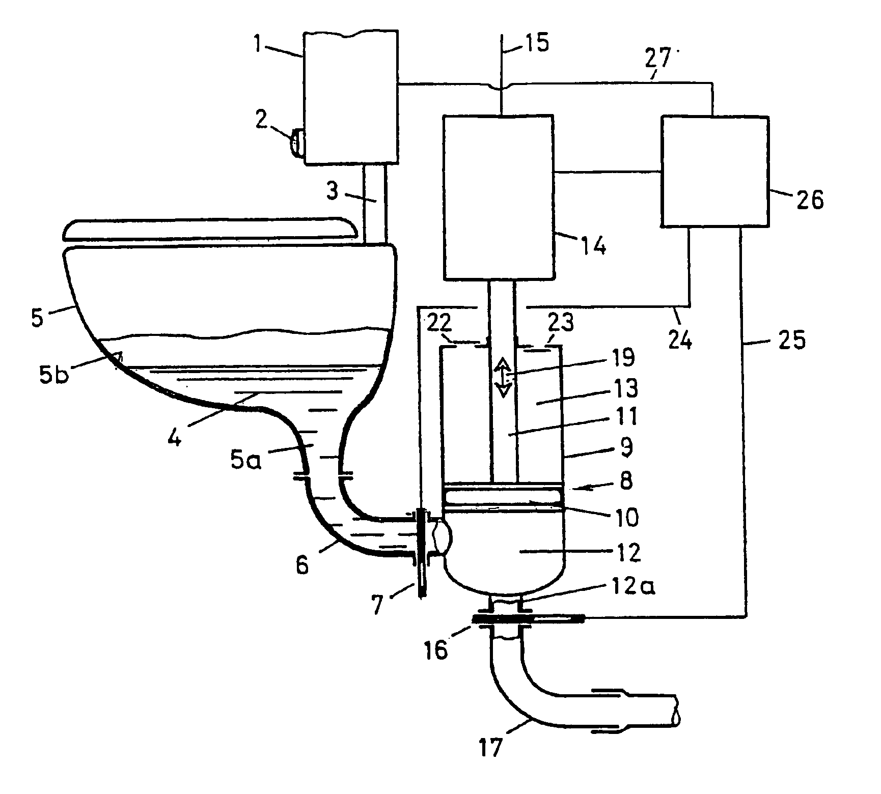
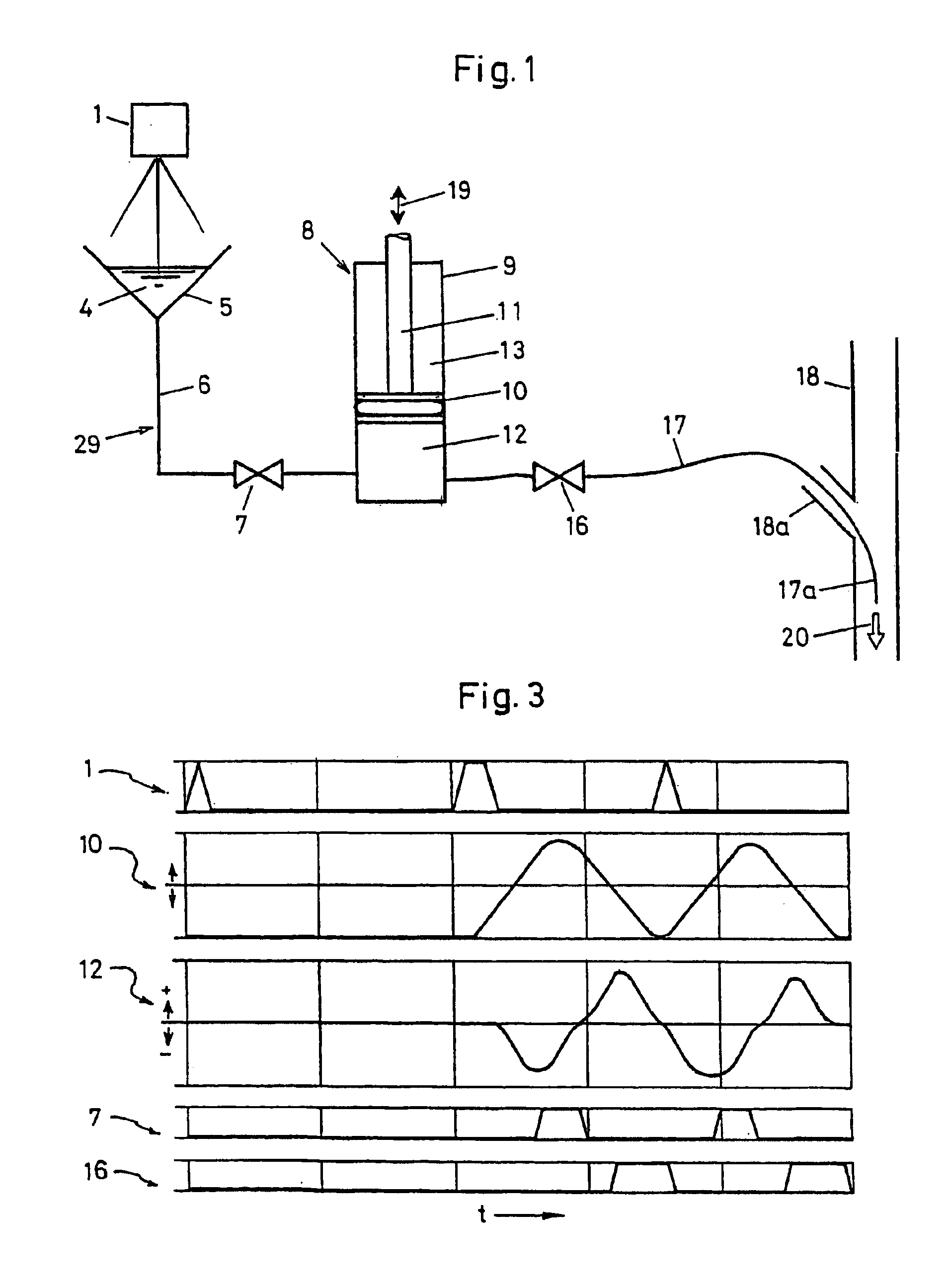
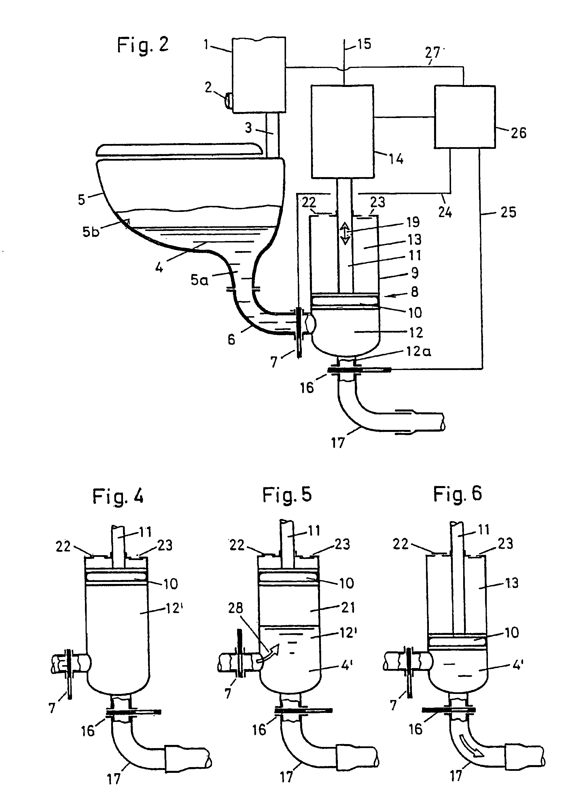
[0010]This object is achieved, in the case of a toilet system of the generic type, in that the pressure chamber is designed as a piston cylinder, and the piston is connected to a controllable drive in order to produce the positive pressure and negative pressure. In the case of the toilet system according to the invention, the negative pressure and positive pressure are produced by movement of the piston. This allows a very quick build-up of a negative pressure, for example within a fraction of a second. A positive pressure may likewise be produced very quickly and, in addition, with a positive pressure of more than 1 bar, for example approximately 2 bar. A further advantage of the toilet system according to the invention is that the displacement, and thus the volume of the substance which can be extracted by suction, can be adjusted precisely. It is also possible for two or more suction-extraction cycles to be carried out one after the other. A satisfactory flushing operation is thus possible with a very small amount of water. The piston of the piston cylinder here may itself serve as sealing means for preventing foul air from escaping outward. There is thus no need for a flexible membrane or the like. According to a development of the invention, the piston is moved by means of an electric motor. In conjunction with a control arrangement, this allows precise control of the suction-extraction and expelling operations. These operations, in addition, can be adjusted and adapted to the respective toilet pan.

Problems solved by technology

Collecting tanks require a large amount of space and have to be emptied.
They are not desirable for domestic use.
The problem with this toilet system is that sealing the chamber by means of a flexible membrane involves high outlay and is fault-prone.
In order to build up a negative pressure, an ejector pump requires a comparatively long period of time.
In addition, the pressure which can be achieved in order to expel the substance from the chamber is very limited.
This toilet system is not likely to prove successful in practice.

Method used


Image

  • Toilet system with a toilet pan
  • Toilet system with a toilet pan
  • Toilet system with a toilet pan

Examples


Embodiment Construction

[0015]According to FIGS. 1 and 2, the toilet system has a toilet pan 5 which is of hopper-like design and has a bottom outlet 5a. This outlet 5a, however, is comparatively small and has a cross section of, for example, 30 mm2. Connected to the underside of this outlet 5a, in a conduit 29, is a suction line 6, which likewise has a comparatively small cross section. The toilet pan 5 can be flushed by a flushing arrangement 1, and has a flushing pipe 3 through which flushing water can be directed into the interior of the toilet pan 5. The flushing arrangement 1 may be a flushing cistern or some other suitable flushing arrangement. The essential factor, however, is that use is made of a comparatively small amount of flushing water, for example less than 1 liter. The flushing is triggered by a button 2 or by some other suitable triggering arrangement. Contactless or automatic triggering is also conceivable here.

[0016]The suction line 6 contains a valve 7 which, in a closed state, closes ...


PUM


Abstract

A toilet system which can be rinsed by a rinsing device. A pipe is connected to the toilet pan and leads to a sanitation pipe. Means are provided for transporting a suction material from the toilet pan into the pipe and into the sanitation pipe. Said means comprise two valves which are arranged in the pipe and a pressure chamber is disposed in-between. In order to suction the suction material from the toilet pan, low pressure is produced in the pressure chamber and used to transport said suctioned material. The pressure chamber is embodied as a piston cylinder and the piston is connected to a controllable drive in order to produce the high and low pressure. The inventive toilet system enables rinsing to occur using a very small amount of water and which can be adapted to different toilet pans.

Description

BACKGROUND OF THE INVENTION[0001]1. Field of the Invention[0002]The invention relates to a toilet system with a toilet pan, which can be flushed by a flushing arrangement, having a conduit which is connected to the toilet pan and leads to a waste-disposal conduit, having means for transporting a suction-extraction substance from the toilet pan into the conduit and into the waste-disposal conduit, the means having, in the conduit, two valves and, between the latter, a pressure chamber in which it is possible to produce a negative pressure, for the suction extraction of the substance from the toilet pan, and a positive pressure, for transporting the substance, once extracted by suction, into the waste-disposal conduit.[0003]2. Description of the Related Art[0004]Up until now, toilet systems in which the suction-extraction substance is extracted by means of a vacuum have been known, in particular, in vehicles, for example in railroad cars and RVs. For example, WO 92 / 18713 discloses a t...

Claims


Application Information

Patent Timeline
Patent Type & Authority Patents(United States)
IPC IPC(8): E03F1/00E03D5/00
CPCE03F1/006E03D5/00
Inventor BREIING, ALOISWERNER, UWE
Owner GEBERIT INT AG
Learn More