
Preforms for forming machined structural assemblies

Inactive Publication Date: 2005-06-28
THE BOEING CO
View PDF40 Cites 49 Cited by
  • Summary
  • Abstract
  • Description
  • Claims
  • Application Information

AI Technical Summary

Benefits of technology

[0005]The present invention provides an improved preform, machined structural assembly, and associated methods of forming the same. In one embodiment, the present invention provides a preform for use in forming a machined structural assembly of predetermined dimensions. The preform includes a first structural member defining at least one contact surface and a second structural member defining at least one contact surface that corresponds to the contact surface of the first structural member. A friction weld joint joins the contact surfaces of the first and second structural members to thereby form a preform having dimensions approximating the dimensions of the final machined structural assembly so as to reduce material waste and machining time when forming the assembly. In one embodiment, the first and second structural members comprise aluminum, aluminum alloys, titanium, titanium alloys, nickel-based, steel, copper-based alloys, or beryllium-based alloys. In another embodiment, the first and second structural members comprise dissimilar materials. In still another embodiment, the preform comprises a third structural member friction welded to at least one of the first and second structural members.
[0009]Accordingly, there is provided a preform for forming machined structural assemblies having dimensions approximating the dimensions of the machined structural assembly to thereby reduce material waste and machining time. The dimensions of the machined structural assembly are not limited by the sizes of stock materials. Advantageously, the friction weld between the structural members provides a strong material bond with the formation of negligible residual stresses. Thus, the preform of the present invention facilitates the efficient production of structural assemblies having consistent material properties and dimensional tolerances.

Problems solved by technology

Thus, while hogout machining provides a method for forming structural assemblies having complex configurations, hogout machining can be costly due to the relatively large amount of excess material or scrap that typically must be removed and because the machining process can be time consuming and labor intensive.
Hogout machining also can cause excessive wear on the cutting machine and tools, which can result in machine downtime and / or tool breakage that in turn can adversely affect the tolerances of the finished assembly.
In addition, the availability of stock sizes of material limits the overall dimensions of a structural assembly formed by hogout machining.
However, the production of forged stock material can be time consuming and labor intensive and, in the case of die forgings, can require the production of costly forging dies.
Die forgings can require ultrasonic inspection, as the forging process can cause internal cracks or other defects.
Additionally, both die and hand forging can cause residual stresses in the forged stock material that can remain in the finished structural assembly.
Residual stresses can necessitate slower cutting speeds when hogout machining and can adversely affect the material properties and tolerances of the finished assembly.

Method used


Image

  • Preforms for forming machined structural assemblies
  • Preforms for forming machined structural assemblies
  • Preforms for forming machined structural assemblies

Examples


Embodiment Construction

[0030]The present invention now will be described more fully hereinafter with reference to the accompanying drawings, in which preferred embodiments of the invention are shown. This invention may, however, be embodied in many different forms and should not be construed as limited to the embodiments set forth herein; rather, these embodiments are provided so that this disclosure will be thorough and complete, and will fully convey the scope of the invention to those skilled in the art. Like numbers refer to like elements throughout.

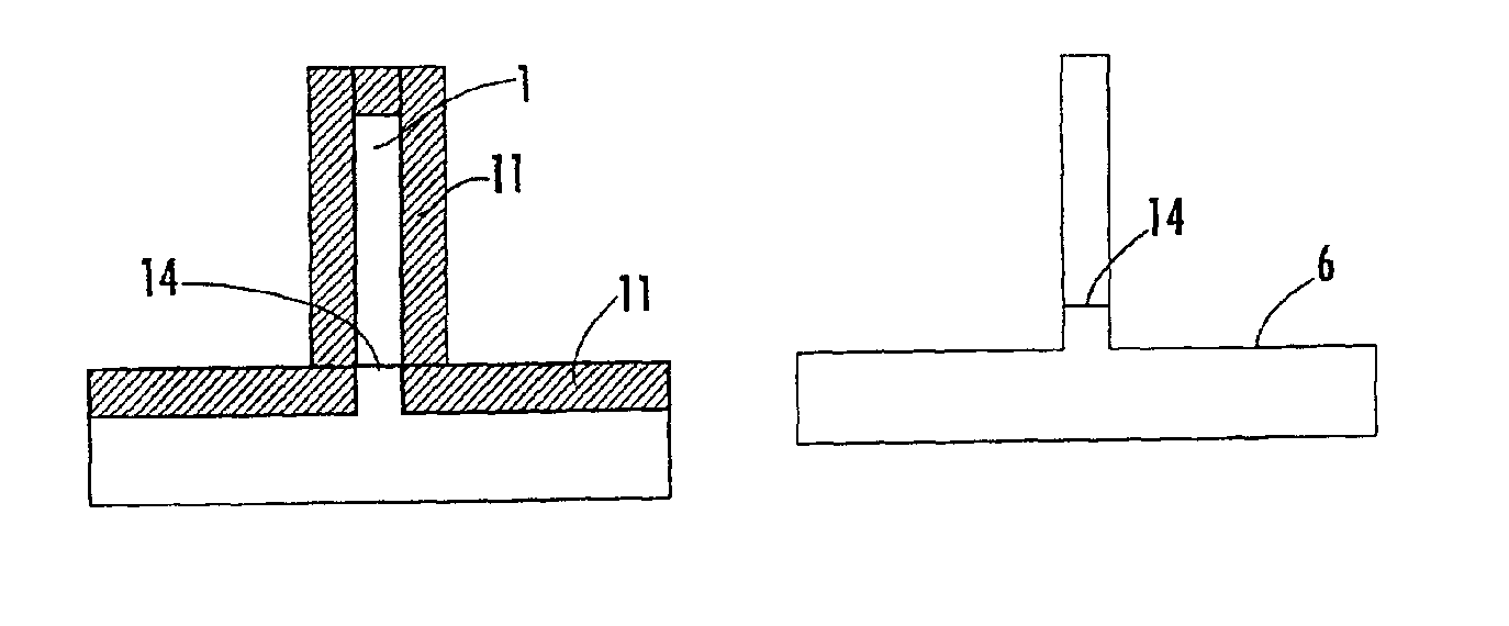
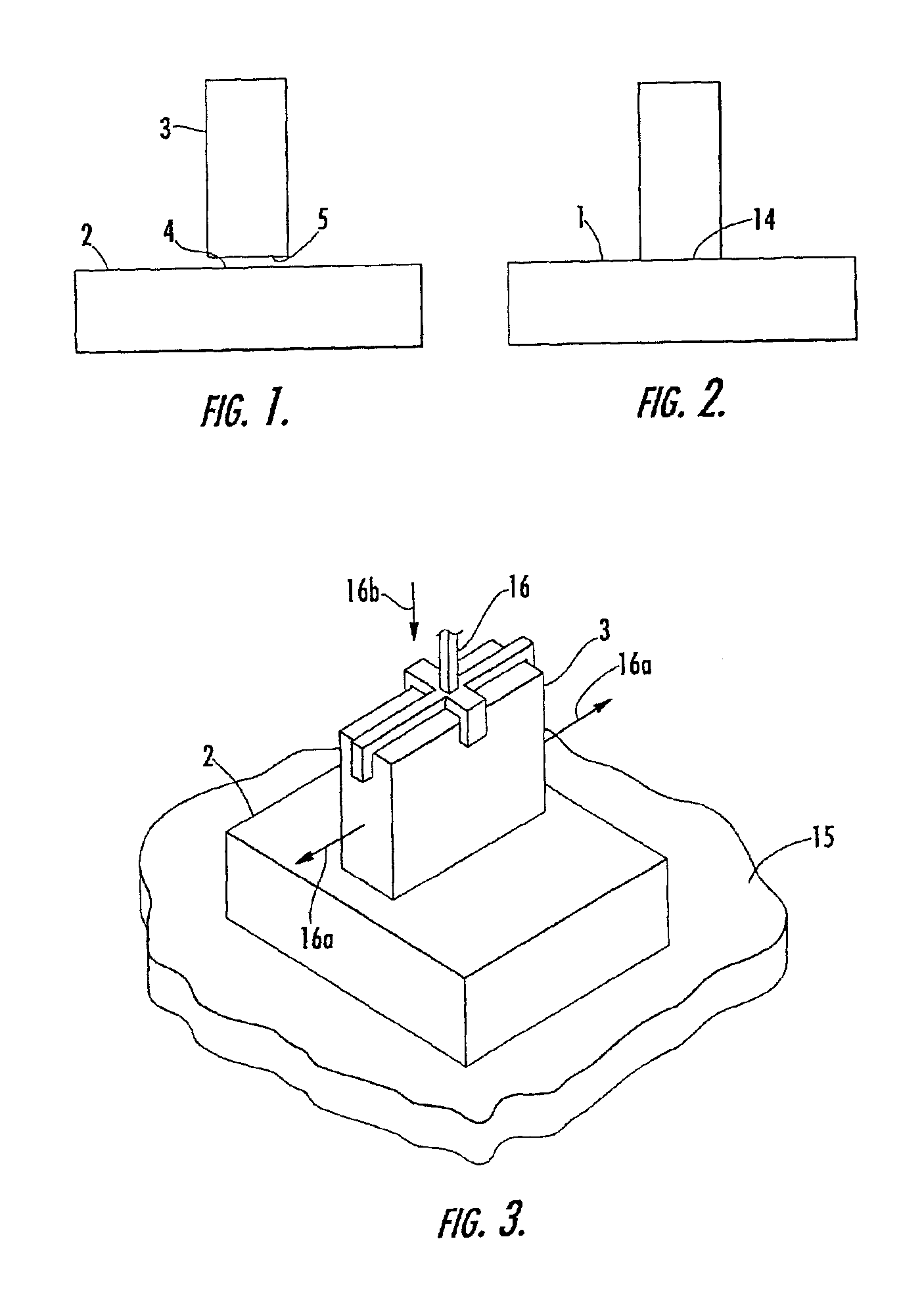
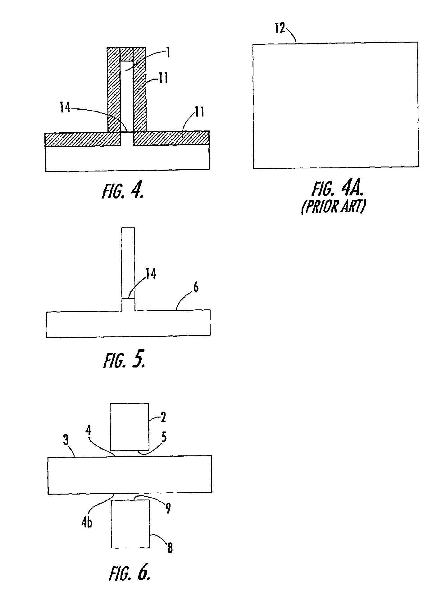
[0031]Referring to the drawings and, in particular, to FIGS. 1, 2, 3, 4, and 5, there is illustrated the formation of a machined structural assembly 6 from a preform, according to one embodiment of the present invention. As illustrated in FIGS. 1, 2, and 3, the preform 1 is formed from a first structural member 2 and a second structural member 3. In other embodiments, as illustrated in FIGS. 6 and 7, the preform 1 is formed from three or more structural me...


PUM

PropertyMeasurementUnit
Massaaaaaaaaaa
Dimensionaaaaaaaaaa
Surfaceaaaaaaaaaa

Abstract

A method of constructing a preform for use in forming a machined structural assembly is provided. The method includes determining the dimensions of the machined structural assembly. First and second structural members are selected based on the predetermined dimensions of the machined structural assembly. The first structural member is positioned adjacent the second structural member so as to define at least two contact surfaces. The contact surfaces of the first and second structural members are friction welded to construct the preform such that the preform has dimensions approximating the dimensions of the machined structural assembly to thereby reduce material waste when forming the machined structural assembly. A machined structural assembly having predetermined dimensions is formed from the preform by machining away excess material.

Description

FIELD OF THE INVENTION[0001]This invention relates to friction welding and, more specifically, to friction welding of preforms for use in forming machined structural assemblies.BACKGROUND OF THE INVENTION[0002]Hogout machining generally refers to a process of forming a structural assembly by removing excess material from a piece of stock material, such as a plate or block, to arrive at the desired configuration and dimensions for the assembly. Oftentimes when practicing hogout machining, the dimensions and configuration of the structural assembly are such that appreciable amounts of material must be removed. Thus, while hogout machining provides a method for forming structural assemblies having complex configurations, hogout machining can be costly due to the relatively large amount of excess material or scrap that typically must be removed and because the machining process can be time consuming and labor intensive. Hogout machining also can cause excessive wear on the cutting machi...

Claims


Application Information

Patent Timeline
IPC IPC(8): B23K20/12
CPCB23K20/129
Inventor HALLEY, JEREMIAH E.SLATTERY, KEVIN T.
Owner THE BOEING CO
Learn More