ACF tape feeder machine, and method for feeding ACF tape

a feeder machine and acf tape technology, applied in the direction of mechanical control devices, instruments, photosensitive materials, etc., can solve the problems of troublesome and time-consuming, large time loss, and difficulty in connecting electrodes on the side of the driver electronics parts to electrodes on the side of the substra

Inactive Publication Date: 2005-06-28
HITACHI HIGH-TECH ELECTRONICS ENGINEERING CO LTD
View PDF4 Cites 1 Cited by
  • Summary
  • Abstract
  • Description
  • Claims
  • Application Information

AI Technical Summary

Benefits of technology

[0011]In view of the foregoing situations, it is an object of the present invention to make it possible to replace an empty ACF tape supply reel by a fresh reel and to connect a fore end portion of an ACF tape from the fresh supply reel to a bonding means of an ACF tape feeder machine quickly and smoothly, permitting to set a fresh supply reel in a stand by position at any time or in an arbitrary timing, irrespective of the progress of a current tape feeding operation.
[0012]It is another object of the present invention to make it possible to carry out a reel replacing job and a tape end connecting job separately in different timings, permitting to carry out a reel replacing job concurrently or in overlapped relation with an ACF tape feeding operation from other supply reel.
[0013]It is still another object of the present invention to make it possible to shorten the time for reel replacements and to permit an uninterrupted ACF taple feeding operation by the use of ACF tape supply reels each loaded with a limited length of ACF tape.

Problems solved by technology

No matter which mounting method is employed, it is difficult to use solder in connecting electrodes on the side of the driver electronics parts to electrodes on the side of the substrate, which are formed in an extremely fine pitch.
Heretofore, the reel replacing and tape end connecting jobs have relied on manual labor of an operator despite the fact that these jobs are troublesome and time consuming.
Of course, the operation of mounting driver electronics parts on a substrate is suspended during the reel replacement and the tape end connecting operation, resulting in great time losses.
As a result, the operational efficiency is deteriorated considerably by the reel replacements because the operator cannot do other jobs during each standby period.

Method used


Image

  • ACF tape feeder machine, and method for feeding ACF tape
  • ACF tape feeder machine, and method for feeding ACF tape
  • ACF tape feeder machine, and method for feeding ACF tape

Examples


Embodiment Construction

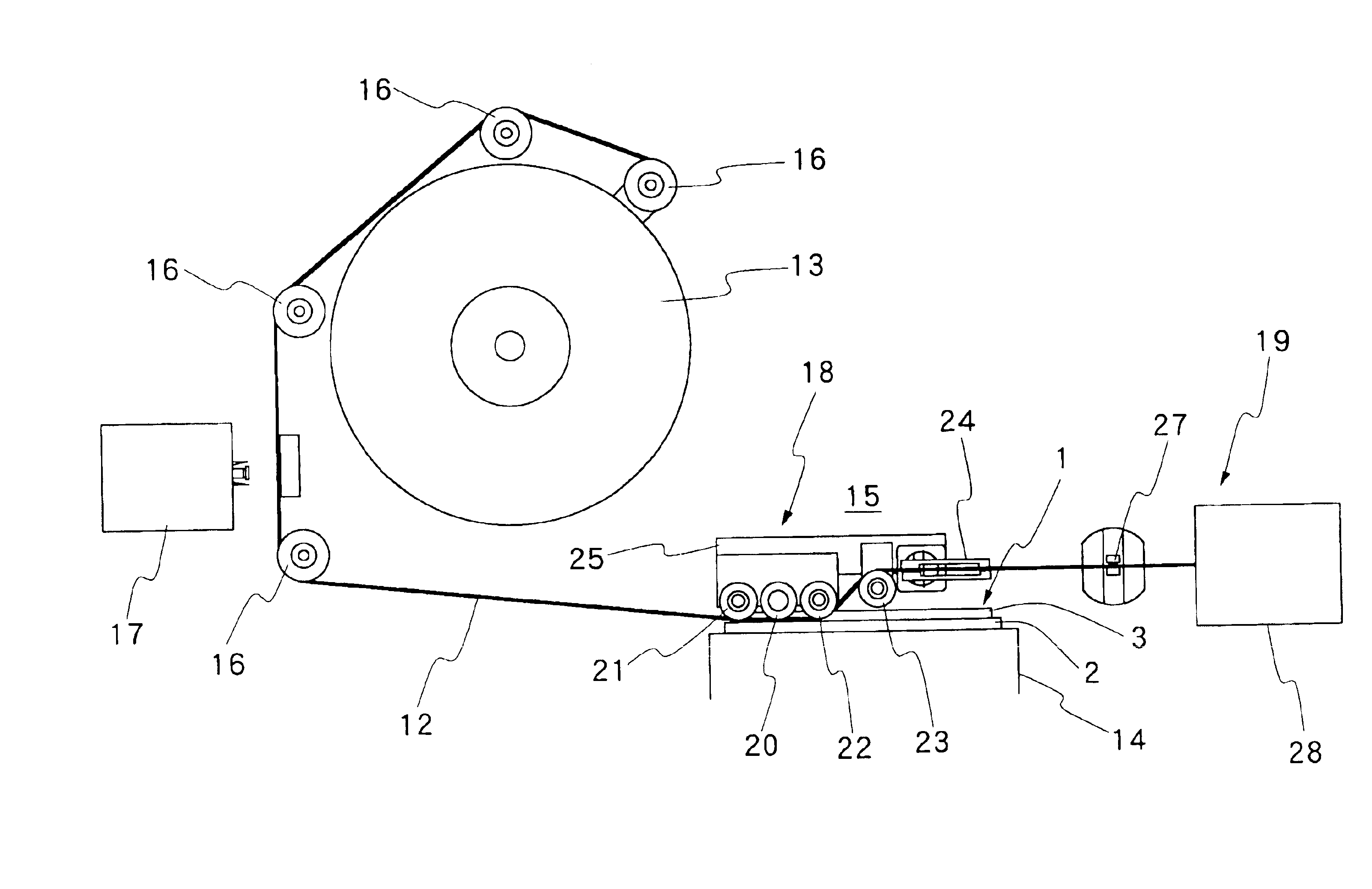
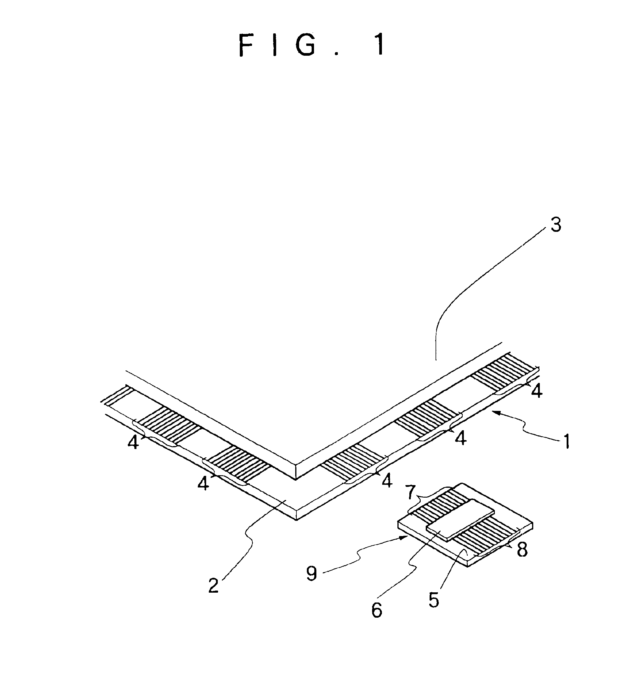
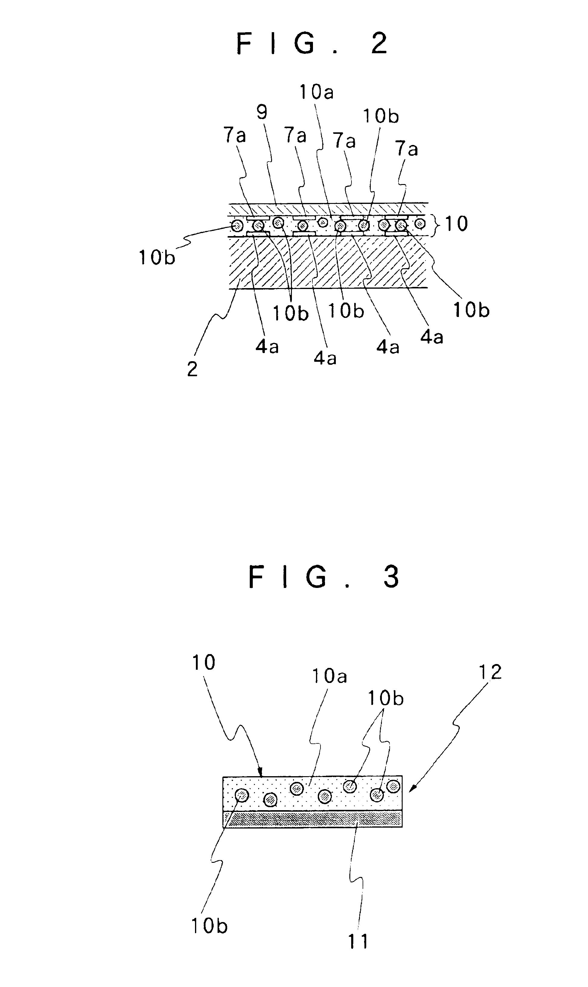
[0034]Hereafter, the present invention is described more particularly by way of its preferred embodiment shown in the accompanying drawings. Firstly, reference is had to the outer view of a liquid crystal cell in FIG. 1, the sectional view of a TAB mount portion in FIG. 2, and the sectional view of ACF tape in FIG. 3.

[0035]In FIG. 1, the liquid crystal cell 1 has liquid crystal sealed in a cell gap which is formed between two overlapped transparent substrate plates, for example, between two substrate plates of glass. Here, the two substrate plates 2 and 3 which constitute the liquid crystal cell 1 are referred to as a lower substrate 2 and an upper substrate 3, respectively. Electrode patterns are formed on confronting inner surfaces of the lower and upper substrate plates 2 and 3 by printing or other suitable means, in groups each consisting of a plural number of electrodes as indicated by reference numeral 4. In the case of the lower substrate plate 2, for instance, groups of elec...


PUM

PropertyMeasurementUnit
angleaaaaaaaaaa
suction forceaaaaaaaaaa
timeaaaaaaaaaa

Abstract

From a supply reel which is set in position at an ACF (Anisotropic Concuctive Film) feeding station, an ACF tape having an ACF laminated on one side of a liner tape is drawn out by an ACF bonding means. At least two reel mount members are provided on a reel stand at the ACF feeding station to mount two ACF tape supply reels concurrently thereon. The reel stand is connected to a switch means thereby to switch the two reel mount members either to an operating or tape supplying position or a standby position. As soon as an ACF tape from a supply reel in the operating position is consumed completely, a fresh supply reel in the standby position is switched into the operating position to continue the supply of the ACF tape.

Description

BACKGROUND OF THE INVENTION[0001]1. Field of the Art[0002]This invention relates to an ACF (Anisotropic Conductive Film) tape feeder machine and a method for feeding ACF tape, suitable for use in feeding and bonding ACF on substrate plates, for example, suitable for use in a liquid crystal display panel fabrication process for bonding ACF on a transparent substrate plate of a liquid crystal cell for the purpose of mounting driver electronics thereon.[0003]2. Prior Art[0004]For example, driver electronics including a plural number of IC devices are connected to at least two side edges of a transparent substrate of a liquid crystal display panel. In some cases, the driver electronics are constituted by IC devices themselves. In some cases, IC devices are mounted on a film substrate to constitute driver electronics parts to be mounted on a transparent substrate or to be connected between a transparent substrate and a printed circuit board.[0005]No matter which mounting method is employ...

Claims


Application Information

Patent Timeline
Patent Type & Authority Patents(United States)
IPC IPC(8): H01L21/00H05K3/36H05K3/32G02F1/1345G02F1/13H01L21/60
CPCH01L21/67132Y10T156/1712H05K3/361H05K3/323G02F1/13
Inventor ONOSHIRO, JUNWADA, KENYAANDO, ICHIYO
Owner HITACHI HIGH-TECH ELECTRONICS ENGINEERING CO LTD
Why Eureka
Try Eureka