Optical material, and, optical element, optical system and laminated diffractive optical element using it

a technology of optical elements and optical materials, applied in the field of optical materials for optical elements, can solve the problems of reducing diffraction efficiency and difficulty in obtaining sufficient correction of chromatic aberration, and achieve the effects of improving diffraction efficiency, reducing diffraction efficiency, and high dispersion

Inactive Publication Date: 2005-06-28
CANON KK
View PDF12 Cites 57 Cited by
  • Summary
  • Abstract
  • Description
  • Claims
  • Application Information

AI Technical Summary

Benefits of technology

[0013]The present invention provides an optical material and an optical element having improved diffraction efficiency over the entire visible region without reduction of diffraction efficiency in certain wavelength regions, taking into consideration not only high dispersion (small Abbe number) but also the relationships between refractive index (nd) and Abbe number (νd), and between Abbe number (νd) and second order dispersion (θg,F).

Problems solved by technology

Thus, it is difficult to obtain sufficient correction of chromatic aberration when there is limitation in the configuration and number of available lenses or in available glass materials.
However, the mere use of a material high in dispersion (small in Abbe number) is not sufficient for further function improvement of a diffractive optical element because there occurs some partial reduction of the diffraction efficiency in the working wavelength region even if the overall diffraction efficiency in the whole visible region is increased. FIG. 2 is a graph showing the diffraction efficiency of a multilayer diffractive optical element for which polyvinylcarbazole is utilized as the material high in dispersion.

Method used


Image

  • Optical material, and, optical element, optical system and laminated diffractive optical element using it
  • Optical material, and, optical element, optical system and laminated diffractive optical element using it
  • Optical material, and, optical element, optical system and laminated diffractive optical element using it

Examples


example 1

[0064]The structure of a laminated diffractive optical element and a manufacture method thereof are described in this Example 1 with reference to FIGS. 5A, 5B and 5C to 8.

[0065]First, to 100 g of a 4.4 wt % dispersion in chloroform of ITO nanoparticles of 10 nm average particle size, 12 g of styrene monomer and 0.15 g of 1-hydroxycyclohexylphenyl ketone as photoinitiator were added, and then chloroform was removed under reduced pressure to obtain an optical raw material 2.

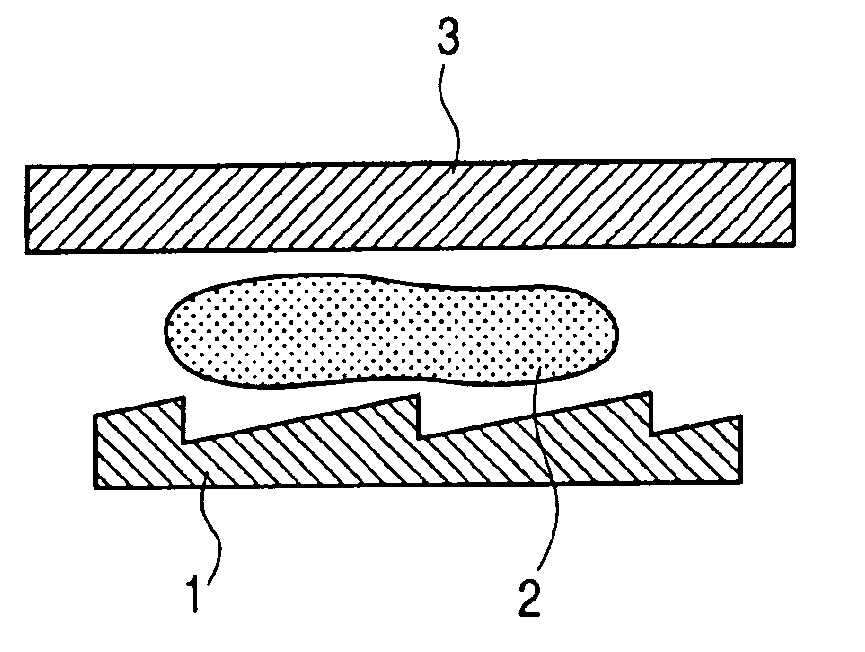
[0066]Then, as shown in FIG. 5A, the optical raw material 2 was put in a mold 1 machined for a diffraction grating. Subsequently, as shown in FIG. 5B, a flat glass plate 3 (BK7) was laid on the optical material 2, and irradiation was made with a dose of 20,000 mJ / cm2 (100 mW / cm2, 200 seconds) using a UV irradiation system (EX250: manufactured by HOYA-SCHOTT Co.). Then, as FIG. 5C shows, the cured optical material 2′ was released from the mold 1 as a diffractive optical element 4. During UV cure of the optical raw m...

example 2

[0070]The structure of a laminated diffractive optical element and a manufacture method thereof are described in this Example 2 with reference to FIGS. 9A to 9C, 6A to 6C, 10 and 11.

[0071]First, to 100 g of a 8.8 wt % dispersion in chloroform of ITO nanoparticles of 10 nm average particle size, 12 g of styrene monomer and 0.15 g of 1-hydroxycyclohexylphenyl ketone as a photoinitiator were added, and then chloroform was removed under reduced pressure to obtain an optical raw material 12.

[0072]Then, as shown in FIG. 9A, the optical raw material 12 was put in a mold 11 machined for a diffraction grating. Subsequently, as shown in FIG. 9B, a flat glass plate 13 (BK7) was laid on the optical material 12, and irradiation was made with a dose of 20,000 mJ / cm2 (100 mW / cm2, 200 seconds) using a UV irradiation system (EX250: manufactured by HOYA-SCHOTT Co.). Then, as FIG. 9C shows, the cured optical material 12′ was released from the mold 11 as a diffractive optical element 14. During UV cure...

example 3

[0076]The structure of a laminated diffractive optical element and a manufacture method thereof are described in this Example 3 with reference to FIGS. 12A to 12C, 6A to 6C, 13 and 14.

[0077]First, to 200 g of a 10 wt % dispersion in chloroform of ITO nanoparticles of 10 nm average particle size, 12 g of styrene monomer and 0.15 g of 1-hydroxycyclohexylphenyl ketone as a photoinitiator were added, and then chloroform was removed under reduced pressure to obtain an optical raw material 22.

[0078]Then, as shown in FIG. 12A, the optical raw material 22 was put in a mold 21 machined for a diffraction grating. Subsequently, as shown in FIG. 12, a flat glass plate 23 (BK7) was laid on the optical material 22, and irradiation was made with a dose of 20,000 mJ / cm2 (100 mW / cm2, 200 seconds) using a UV irradiation system (EX250: manufactured by HOYA-SCHOTT Co.). Then, as FIG. 12C shows, the cured optical material 22′ was released from the mold 21 as a diffractive optical element 24. During UV c...


PUM

PropertyMeasurementUnit
Abbe numberaaaaaaaaaa
sizeaaaaaaaaaa
Abbe numberaaaaaaaaaa

Abstract

An optical element of which diffraction efficiency hardly varies with wavelength is provided by using an optical material satisfying the conditions that nd>−6.667×10⁻³vd+1.70 and θg,F≦−2×10⁻³νd+0.59 where nd is a refractive index at d-line, νd is an Abbe number at the d-line, and θg,F is a second order dispersion at d-line, whereby diffraction efficiency is improved in any working visible wavelength region and more precise chromatic aberration correction is obtained.

Description

BACKGROUND OF THE INVENTION[0001]1. Field of the Invention[0002]The present invention relates to an optical material for optical elements such as refractive optical elements and diffractive optical elements. More specifically, the present invention relates to an optical material with high dispersion (wide variation of refractive index with wavelength), and optical elements, diffractive optical elements and laminated diffractive optical elements molded therefrom.[0003]2. Related Background Art[0004]In conventional refractive optical systems based on solely light refraction, chromatic aberration has been reduced by combination of glass materials different in dispersion characteristics. For example, in a telescope, the chromatic aberration of the object lens is corrected by combining a positive lens made of a low-dispersion glass material and a negative lens made of a high-dispersion glass material. Thus, it is difficult to obtain sufficient correction of chromatic aberration when ther...

Claims


Application Information

Patent Timeline
Patent Type & Authority Patents(United States)
IPC IPC(8): G02B1/04G02B5/18B32B7/02G02B3/00H01L21/027
CPCG02B1/04G02B5/18G02B5/1847C08L25/06
Inventor UKUDA, HIDEO
Owner CANON KK
Why Eureka
Try Eureka