
Distributed virtual environment

a virtual environment and distribution technology, applied in the field of distributed virtual environments, can solve the problems of lack of scaleability, difficulty in maintaining a common shared view amongst all clients, and difficulty for designers to control what and whom players, so as to ensure the integrity and consistency of the apparatus, and reduce the requirement of upstream traffic

Inactive Publication Date: 2005-06-28
BRITISH TELECOMM PLC
View PDF9 Cites 149 Cited by
  • Summary
  • Abstract
  • Description
  • Claims
  • Application Information

AI Technical Summary

Benefits of technology

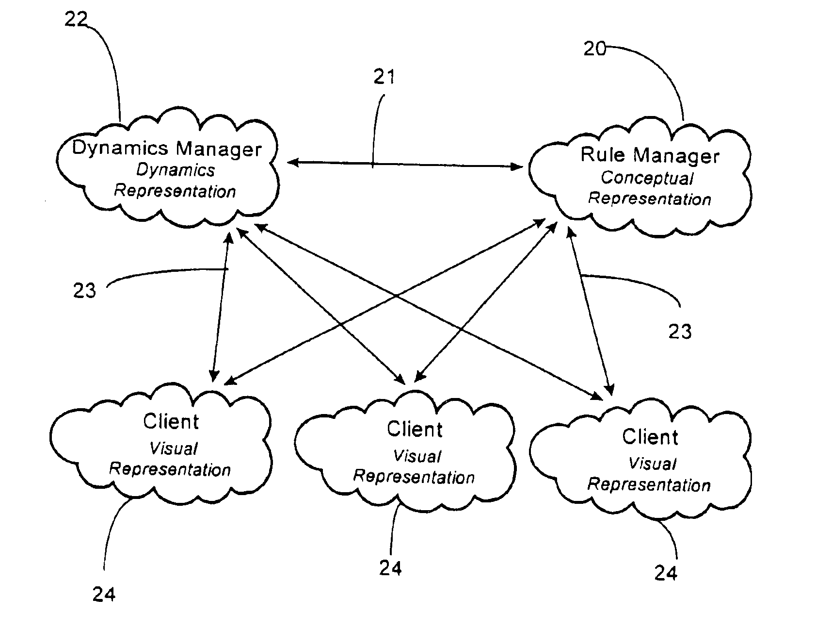
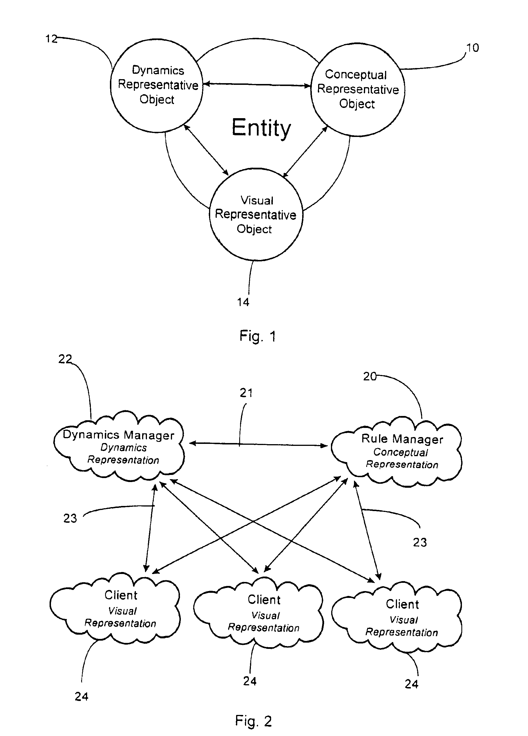
[0027]Separation of the dynamic and conceptual models makes balancing and extending the game far easier. Because the complex dynamics are handled elsewhere, a game designer has a conceptual model to work with that is highly focused on the game play and the game content. Modifying and adding to this will not involve any changes to the dynamic or visual models. Hence, game designers can focus on the issues relevant to the game play, and not on the behaviour and state distribution needed to maintain a shared VE.
[0029]Hence, not only is it easy to vary an existing game, it should be simple to deliver a completely new game by providing a new set of conceptual representatives.
[0031]The embedding of many of the game rules into a conceptual model, stored at a server, helps to reduce the upstream traffic requirement from each client. Where a client action may make a large number of dynamic changes to an environment (e.g. opening a door which pushes a number of objects aside), the client sends only a single high level request to the rule model manager. This may then be mapped into a large number of dynamic state changes by both the rule model manager and the dynamic model manager(s).
[0032]The combination of both the conceptual models (e.g. the game rules) and the dynamic models ensures the integrity and consistency of the apparatus. Clients can only make changes to the VE after they have been authenticated through either the conceptual models or the dynamic models. Hence players are assured of fair play for all. If the integrity of the environment is breached through users exploiting a code bug, fixes can be applied on the relevant server code. This avoids the need to trust users to install client patches as necessary.

Problems solved by technology

High or variable latency can make it difficult to maintain a common shared view amongst all clients.
It is therefore very difficult for the designer to control what and whom the player encounters during his or her game session.
This approach lacks both scaleability (as the network load at each client grows with every additional client) and persistence (as the environment state is lost when the last client leaves).
This is due to the fact that as client numbers increase both the server network traffic load and processing load increase forcing even the most powerful server to become a bottleneck.
Whilst this has the potential to provide an efficient implementation (each client is effectively custom built for each game title) it limits balancing of the game play over time to the fixed constraints of the release version of the game rules.
Also by associating the game rules so closely with the client implementation it limits reuse of components.
However, these known approaches fail to address the issues directly relevant to gaming namely balance, reuse and integrity.

Method used


Image

  • Distributed virtual environment
  • Distributed virtual environment
  • Distributed virtual environment

Examples


second embodiment

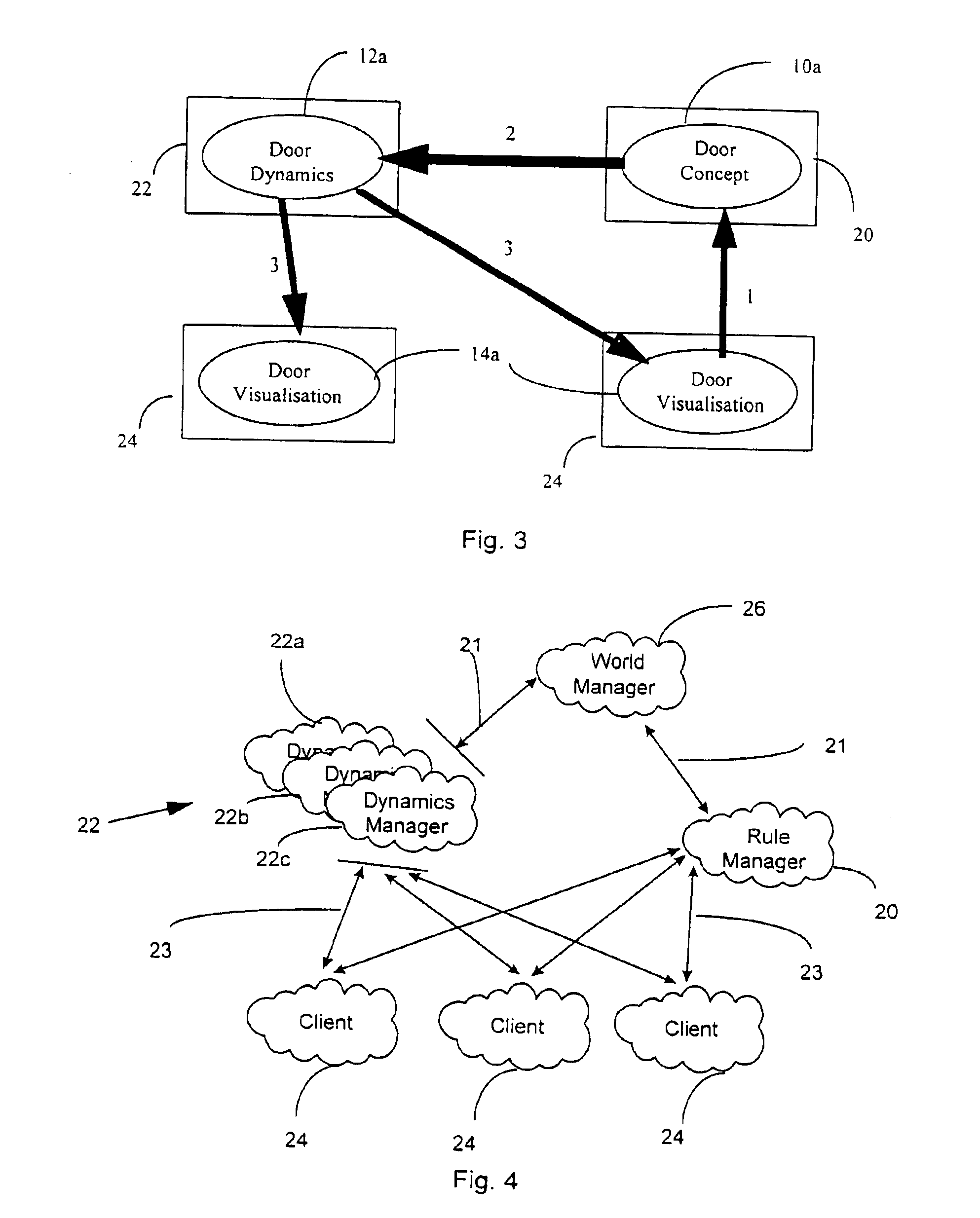
[0083]FIG. 4 shows a preferred second embodiment of the invention based on this approach.

[0084]At the server end a Rule Manager (RM) 20 is provided as per the embodiment of FIG. 1. Several Dynamic Managers (OMs) 22a, 22b, 22c are provided along with a so called World Manager (WM) 26. Whilst the modelling of the dynamics of the environment is distributed, this is invisible to the conceptual model of the environment. The World Manager 26 provides a routing layer which allows the Rule Manager 20 to send messages directly to the Dynamic Manager 22 without having to track the location of the dynamic representative objects in the VE.

[0085]Appropriate communication between RM, WM and DMs is provided by means of respective network connections 21 between the RM 20 and WM 26, and between the WM 26 and each DM 22.

[0086]A further network connection 23 allows communication with one or more clients 24, each of which stores a Visual Representative Object.

[0087]Whilst multiple DMs 22a, 22b, 22c are...

case 3

[0147 is handled in a different way, and relies on allowing running Zone Managers to request one of their neighbouring zones be started. A Zone Manager, on detecting that a dynamic representative object needs to move into a currently closed zone, sends the request to the World Manager. The World Manager performs the creation process and the original Zone Manager will receive a connection from the new Zone Manager as it starts.

[0148]The start-up process for a Zone Manager 28 is as follows:[0149]Establish network connection from World Manager 26 to a zone manager 28.[0150]Receive allocated zone identity from World Manager, and extract current state of zone from the persistent object store 29.[0151]Create all dynamic representative objects within allocated zone from extracted state description.[0152]Receive identity of neighbouring zones, and, for those neighbours currently started, receive an address suitable to establish a network connection.[0153]For all neighbouring zones not start...


PUM


Abstract

A distributed virtual environment includes one or more entities represented in the virtual environment by at least a conceptual entity-model, a dynamic entity-model and a visual entity-model each of the entity models being mutually independent. A server provides a conceptual-model manager, arranged to provide conceptual entity-models, one or more dynamic-model managers arranged to provide dynamic entity-models, and one or more client apparatuses arranged to provide a visual-model manager arranged to provide visual entity-models. Communications is arranged to allow transmission of messages between the conceptual-model manager, one or more dynamic-model managers and one or more visual-model managers.

Description

RELATED APPLICATION[0001]This application is related to copending commonly assigned application Ser. No. 09 / 743,898 filed Jan. 17, 2001.BACKGROUND OF THE INVENTION[0002]The present invention relates to a distributed virtual environment.[0003]Computer and video gaming has been a popular pastime ever since the first personal computers and home video game consoles arrived back in the late 1970s. In the last two or three years the nature of these games has changed dramatically due to development in two technical areas.[0004]Firstly increasing computer power has allowed complex 3-D virtual environments to be modelled and displayed. These environments allow players both to move through a virtual world and to interact with the entities within it.[0005]Secondly the widespread growth in computer network usage and availability (e.g. corporate LANs and the internet) has led to many games boasting multi-player capabilities.[0006]Taken together these two developments have resulted in the basis f...

Claims


Application Information

Patent Timeline
Patent Type & Authority Patents(United States)
IPC IPC(8): A63F13/12G06T15/00G06F19/00G06F17/30
CPCG06T15/00A63F13/12A63F13/30A63F13/35
Inventor POWERS, SIMON JHINDS, MICHAEL RMORPHETT, JASON
Owner BRITISH TELECOMM PLC
Learn More