Method of forming a winding disc for an axial field electrical machine

a technology of axial field electrical machines and winding discs, which is applied in the direction of electrical apparatus, dynamo-electric machines, electromagnets, etc., can solve the problems of inpractical stator construction, the practical limit of how close the rotor can be brought to the stationary stator, and the inability to meet the requirements of axial thickness, etc., to achieve the effect of reducing axial thickness, providing additional mechanical strength, and protecting against abrasion

Inactive Publication Date: 2005-07-05
TURBO GENSET
View PDF8 Cites 7 Cited by
  • Summary
  • Abstract
  • Description
  • Claims
  • Application Information

AI Technical Summary

Benefits of technology

[0019]As indicated above, the method of the present invention provides a way of forming a winding disc which, whilst including cross-over sections or bridging portions, can still be reduced in thickness to the same as or less than the thickness of the winding cable itself.
[0020]Once formed, the winding is preferably encapsulated in an electrically insulating material. For example, a thermo-setting resin such as epoxy may be used, preferably with a suitable powder filler, although other systems of encapsulation may be used. Encapsulation can take place after the pressing step once the winding has been formed into the desired shape and thickness. Alternatively, the windings may be coated with the uncured resin prior to pressing and then the resin may be consolidated during the pressing process. In this way excess resin and air can be expelled.
[0021]One or more sheets of fibreglass mat may be added to one or both sides of the winding prior to curing of the encapsulation material. In this way, the mats are incorporated into the structure of the winding disc to provide additional mechanical strength to the otherwise relatively thin winding discs.
[0022]During the pressing step, high forces are applied to the winding which are initially localised on the bridging portions of the winding. Consequently, a thin small sheet of tough insulator such as Kapton® can be placed between the bridging portion of the winding and the part of the winding being bridged. This protects against abrasion between the wires during the pressing step. Once the bridging portions are compacted, the entire stator can be further reduced in axial thickness by additional pressing.
[0023]After pressing, the dimension of the bridging portion in the axial direction of the machine is preferably reduced to less than 50% of the original diameter of the cable more preferably to less than 30% and even more preferably to less than 20% of the original diameter. The width of the cable in the plane of the stator disc will correspondingly increase, conserving volume. The dimensions of the windings beneath the bridging portion, in the axial direction of the machine, are preferably reduced to less than 75% of the original diameter of the cable and more preferably to less than 65%. Advantageously, these windings fill the spaces between each other, in the region beneath the bridging portion.

Problems solved by technology

Axial flux electrical machines offer many advantages over conventional machines but there are considerable technical challenges to overcome to achieve practical and efficient machines.
However, there is a practical limit to how close the rotors can be brought to the stationary stator.
Whilst this arrangement is perfectly acceptable for low speed devices, such as motors for magnetic disc drives, when the machine is required to operate at high speeds (to provide high power density) then such stator constructions are not practical.
The reason for this is eddy current losses.
This is particularly problematic at high powers, typically above 1 kW.
When operating at high speeds (typically above about 10000 rpm) and hence high frequencies, a number of parasitic effects become significant and can significantly reduce the efficiency of the machine if ignored.
Thus if the conductor is solid and large in cross-sectional area to allow for high currents, the losses due to such eddy currents are unacceptable.
Consequently it is undesirable to have any connections within the winding because this makes the construction of the stator extremely complicated and expensive and also reduces the reliability of the finished stator.
This presents a problem in terms of forming a thin stator disc because if the winding is to be formed as a single continuous winding without connections, each of the coil sectors must be formed from the same winding.
This is physically extremely difficult to achieve.
All this would result in a very thick stator disc and consequently a very large air gap between pairs of rotor discs, leading to poor magnetic field strength and efficiency.
Cooling of a thicker disc is also more difficult due to the increased distance for the heat to travel axially.
However, this still results in the problem of having a stator winding disc which has a thickness at least twice the diameter of the winding cable.

Method used


Image

  • Method of forming a winding disc for an axial field electrical machine
  • Method of forming a winding disc for an axial field electrical machine
  • Method of forming a winding disc for an axial field electrical machine

Examples


Embodiment Construction

[0035]A specific embodiment of the present invention will now be described in detail by reference to the accompanying drawings.

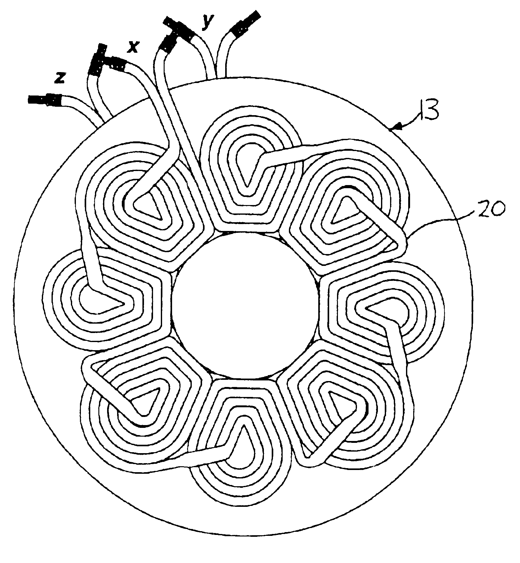
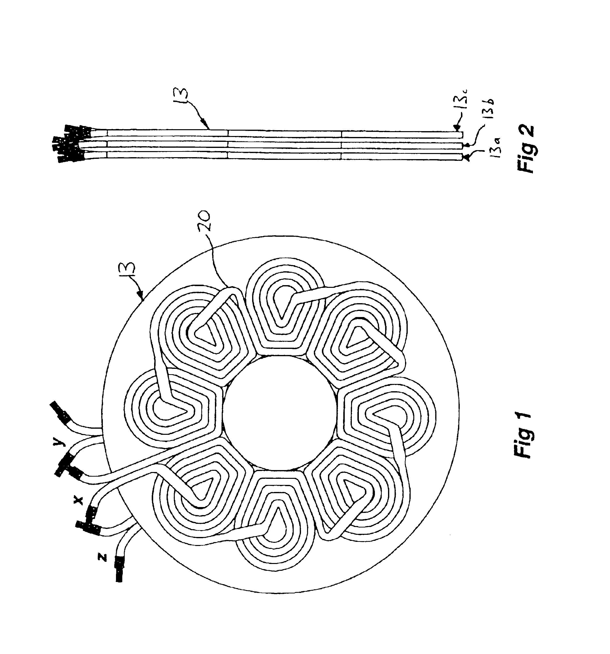
[0036]FIGS. 1 and 2 show one embodiment of the present invention. As can be seen in FIG. 2, the stator disc comprises three separate winding discs 13a, 13b and 13c. Each of these winding discs is substantially identical to the other but arranged so that they are angularly offset from each other as can be seen from the three phase connections x, y, z shown in FIG. 1. Each of the winding discs are attached to each other, preferably with a space therebetween to allow cooling fluid to pass through to assist in cooling the stator.

[0037]As indicated above, each of the winding discs is substantially identical. Therefore only one such winding disc is described in detail below.

[0038]FIG. 1 shows a layout of the windings according to one embodiment of the present invention. In this example, the windings are formed from a single continuous cable which is formed into ei...


PUM

PropertyMeasurementUnit
powersaaaaaaaaaa
axial dimensionaaaaaaaaaa
speedsaaaaaaaaaa

Abstract

The invention provides a stator coil construction in which the thickness of the stator windings is reduced without the need for interconnections within the stator. The reduction in thickness of the stator windings is accomplished by wire flattening.

Description

FIELD OF THE INVENTION[0001]The present invention relates to an axial flux rotary electrical machine and in particular an improved stator coil construction for such a machine.BACKGROUND OF THE INVENTION[0002]Axial flux electrical machines offer many advantages over conventional machines but there are considerable technical challenges to overcome to achieve practical and efficient machines. GB-A-2,222,031 and GB-A-2,261,327 both describe axial field machines designed to operate at very high speeds with high efficiency. WO 96 / 38901 describes further improvements to such machines in order to provide a machine which has improved mechanical and electrical reliability as well as improved cooling and electrical characteristics. All these elements combine to provide a machine which is both physically compact but also highly efficient at converting electrical energy into motive power and vice versa.[0003]The construction of a typical axial flux electrical machine is shown in FIG. 11. As can ...

Claims


Application Information

Patent Timeline
Patent Type & Authority Patents(United States)
IPC IPC(8): H02K3/26H02K9/06H02K9/04H02K3/04H02K3/46H02K3/47
CPCH02K3/26H02K9/06H02K3/47Y10T29/49071Y10T29/49073Y10T29/4902Y10T29/49009Y10T29/49012Y10T29/49002
Inventor PULLEN, KEITH ROBERTFENOCCHI, ARNOLDOETEMAD, MOHAMMAD REZA
Owner TURBO GENSET
Why Eureka
Try Eureka