Method and apparatus for producing a composite structural panel with a folded material core

a composite structural and core technology, applied in paper/cardboard articles, constructions, building components, etc., can solve the problems of difficult control and cost of realizing mechanical apparatus, and achieve the effects of improving compressive stiffness and strength, good bonding connection, and expanding the field of application

Inactive Publication Date: 2005-07-05
AIRBUS OPERATIONS GMBH
View PDF11 Cites 54 Cited by
  • Summary
  • Abstract
  • Description
  • Claims
  • Application Information

AI Technical Summary

Benefits of technology

[0014]The core structures produced according to the inventive method are characterized advantageously by a low density and simultaneously by a high bending stiffness and compressive stiffness as well as a high strength, especially in combination with the cover layers arranged and bonded thereon to form the complete structural panel. Due to the particular selected starting material, a good noise insulation characteristic can also be achieved, which can be further improved by perforation of the cover layers. A further advantage of the invention is a significant cost reduction achieved by the substantial increase in the production speed, which is achieved in the continuous fabrication using the method and apparatus of the invention.
[0015]The possibility of folding the starting materials also along curved folded edges rather than or in addition to straight folded edges greatly improves the compressive stiffness and strength and therewith substantially expands the field of application of these core structures, because structures that are folded along curved folded edges are bendable or curvable overall, as opposed to structures that are only folded along straight folded edges. When such a curved or non-planar folded core structure is bonded to curved non-planar cover layers, the curved folded edges of the core structure will lie in contact with the respective upper and lower cover layer along the entire length of the folded edge, and thus may be advantageously glued or otherwise bonded to the respective cover layer along this entire folded edge. This achieves an especially good bonding connection between the core and the cover layers.
[0016]The above objects have further been achieved according to the invention in an apparatus for forming a composite structural panel, and particularly for carrying out the inventive method. The inventive apparatus includes a device or arrangement for pre-treating or pre-processing the starting material web on the upper surface and the lower surface thereof in order to form therein fold lines that will allow a collapsing or buckling of the material web along these fold lines. The apparatus further includes a device or arrangement for initiating the folding process along the previously formed fold lines. The apparatus also includes a device or arrangement for carrying out the additional deformation, reconfiguration, and / or retardation of the material web to further carry out the folding process along the previously initiated folds on the fold lines, with at least one pair of counter-rotating bristle brush rolls or bristle brush conveyor belts. The apparatus still further includes a device or arrangement for post-processing or post-treating the material web from the upper surface and the lower surface thereof in order to stabilize the folded structure by enhancing and / or fixing the folds for example.
[0017]According to a further development of the apparatus according to the invention, at least one counter-rotating pair of rolls, a pair of conveyor belts, or a pair of link chains or belts is provided for carrying out the pre-processing or pre-treatment of the planar starting material web. In this context, at least one of the two rolls, conveyor belts, or link chains or belts has a structured surface, which cooperates with a smooth non-structured surface of the opposite or complementary element to form the fold-lines in the planar starting material web. Throughout this disclosure, the term “structured surface” refers to a surface that is not smooth, but rather includes profiled protrusions such as ridges or the like, at locations in a pattern corresponding to the pattern of fold lines to be formed in the material web. Thus, the respective roll, conveyor belt, or link chain can be provided with protruding ridges, creasing blades, scoring blades, perforating blades or the like, which cooperate with the smooth surface of the counter-roll or other counter element. The smooth surface of the counter element may have an elastic resilient surface covering, to allow the protruding ridges or the like of the structured surface of the other element to press into this resilient surface covering in order to form the fold lines on the material web. Alternatively, the counter-element may have a surface provided with recesses corresponding to and cooperating with the protruding ridges or the like of the opposite roll or other element. In addition to or instead of the just-described elements with a structured surface, the pre-treating arrangement can additionally or alternatively include a device for heating or cooling certain zones of the material web, and / or a device for coating or impregnating the material web.
[0018]According to the invention, the device or arrangement for initiating the folding process along the previously formed fold lines can comprise at least one row of fluid nozzles, preferably compressed air nozzles, which are arranged to be movable relative to the material web. Respective groups or arrays of such nozzles are arranged above and below the material web and are oriented opposite one another so as to direct jets of fluid, e.g. compressed air, onto the upper surface and the lower surface of the material web, e.g along the fold lines and / or at appropriate surface areas for initiating folds along the fold lines. Thereby, the air jets from below the material web push up and initiate the formation of fold peaks in the material web, while the air jets above the material web push down along corresponding fold lines to initiate the formation of fold valleys in the material web.
[0019]A further embodiment of the device or arrangement for initiating the folding process according to the invention comprises a mechanical arrangement that physically contacts and touches the material web either in a point-wise manner or along individual fold lines, both from the upper surface and the lower surface of the material web, so as to begin the folding process. In such a mechanical device, mechanical fingers or protrusions or disk elements take the place of the air jets discussed above in the fluid nozzle arrangement for initiating the folding process.

Problems solved by technology

Therefore, it is difficult, complicated, and costly to realize an actual mechanical apparatus that is to carry out the continuous folding of such a long material web in an exact manner, because a distortion or deformation of the material web arises, which may be within the deformation range of the elastic properties of the, material web and is difficult to control.

Method used


Image

  • Method and apparatus for producing a composite structural panel with a folded material core
  • Method and apparatus for producing a composite structural panel with a folded material core
  • Method and apparatus for producing a composite structural panel with a folded material core

Examples


first embodiment

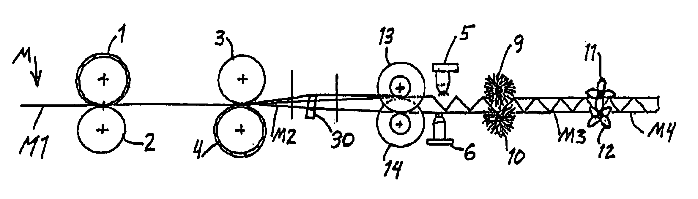
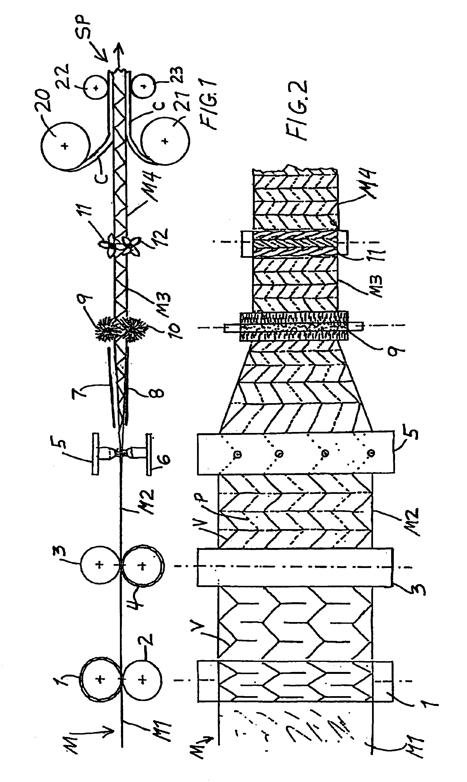
[0036]FIGS. 1 and 2 schematically show an apparatus according to the invention for carrying out the method according to the invention. Namely, the apparatus shown in FIGS. 1 and 2 is for producing a composite structural panel SP including a core structure sandwiched and bonded between two cover layers C. The core structure is produced by folding a material web M, for example of paper or cardboard or resin-impregnated fiber. In the present embodiment, the folding process is a single stage folding process involving a transverse contraction, a longitudinal contraction, and a thickness expansion of the material web M occurring simultaneously. In this folding process, first, fold lines are formed in the initially flat planar configuration M1 of the material web M, and then fold valleys V, shown by solid lines, and fold peaks P, shown by dashed lines, are formed in the material web along the respective associated fold lines.

[0037]More particularly, the apparatus includes a first structure...

second embodiment

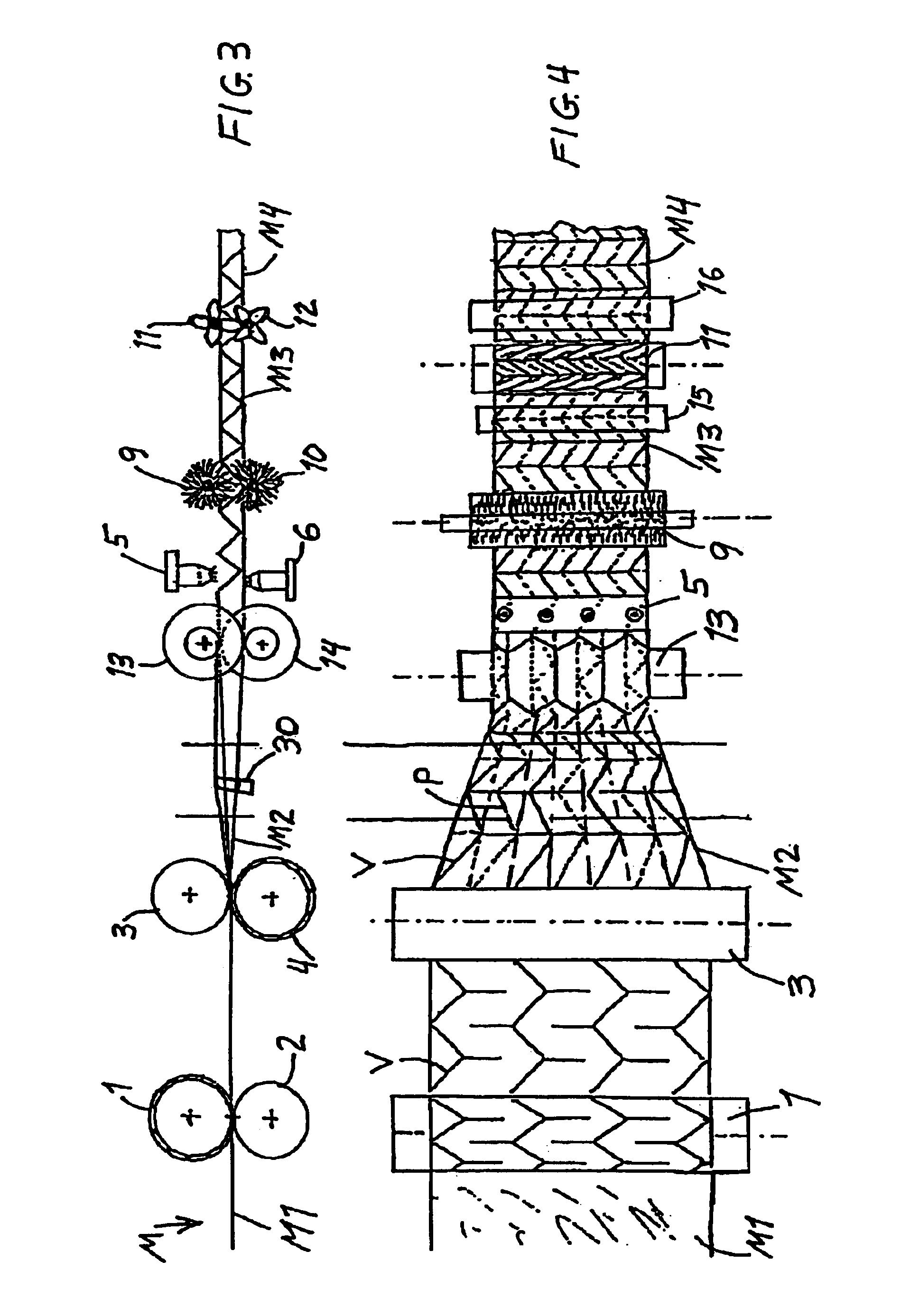
[0045]FIGS. 3 and 4 show an apparatus and method for forming a folded core structure (which can then further be used to form a composite structural panel as described above). The apparatus and process of FIGS. 3 and 4 have much overlap and correspondence with those of FIGS. 1 and 2, and a redundant description of the corresponding components and process steps will be omitted. The same reference numbers are used to identify corresponding features in the embodiment of FIGS. 3 and 4 as in the embodiment of FIGS. 1 and 2.

[0046]The main difference between the first embodiment of FIGS. 1 and 2 and the second embodiment of FIGS. 3 and 4 is that the first embodiment involves a single-stage total compound folding process, while the second embodiment involves a two-stage folding process with a transverse contraction and thickness expansion in a first stage followed by a longitudinal contraction in a second stage. In this regard, the apparatus of FIGS. 3 and 4 comprises an additional of a pair...


PUM


Abstract

A folded core structure is produced by embossing fold lines into a flat planar material web, initiating folds along the fold lines on the upper and lower surfaces of the material web, proceeding with the formation of the folds along the fold lines to deform the material web from its two-dimensional starting configuration to a three-dimensional folded configuration, and post-processing the folded material web to stabilize or fix the folded configuration thereof. A composite structural panel is produced by bonding a cover layer onto at least one surface of the folded core structure. An apparatus preferably includes embossing or creasing rolls to form the fold lines in the material web, air nozzles or folding rolls to initiate the folding process, bristle brush rolls to complete the folding process, and further folding rolls to enhance and fix the folded configuration, optionally in connection with heating, cooling, applying a coating onto, or impregnating a resin or binder into the material web.

Description

PRIORITY CLAIM[0001]This application is based on and claims the priority under 35 U.S.C. §119 of German Patent Application 102 52 941.8, filed on Nov. 14, 2002, the entire disclosure of which is incorporated herein by reference.FIELD OF THE INVENTION[0002]The invention relates to a method as well as an apparatus for producing a lightweight core structure from a web of a thin foldable starting material, and then covering the core structure with one or two cover layers to form a composite structural panel thereof.BACKGROUND INFORMATION[0003]It is generally known to form lightweight structural panels including a lightweight core structure sandwiched between two cover layers. The core structure typically is lightweight yet strong, because it has a configuration including hollow spaces as well as interconnected material webs or the like. Typical examples of such core structures include corrugated sheets, honeycomb cellular structures, and the like. Known core structures have a great vari...

Claims


Application Information

Patent Timeline
Patent Type & Authority Patents(United States)
IPC IPC(8): B31D3/00E04C2/32
CPCB31D3/005E04C2/326
Inventor KEHRLE, RAINER
Owner AIRBUS OPERATIONS GMBH
Why Eureka
Try Eureka