Electron injection composition for light emitting element, light emitting element, and light emitting device

a technology of light emitting elements and compositions, applied in the direction of luminescent compositions, organic semiconductor devices, chemistry apparatus and processes, etc., can solve the problems of difficult to keep amorphous, few suitable materials for forming transparent conductive films, and bcp also has a defect of being easy to crystallize with time, so as to achieve superior injection of electrons, superior properties, and the effect of hard crystallization

Active Publication Date: 2005-07-05
SEMICON ENERGY LAB CO LTD
View PDF12 Cites 41 Cited by
  • Summary
  • Abstract
  • Description
  • Claims
  • Application Information

AI Technical Summary

Benefits of technology

[0015]It is an object of the present invention to provide an electron injection composition for a light-emitting element, which is superior in injecting electrons and is hard to crystallize with time in the case of forming a film to include the electron injection composition, and it is also an object of the present invention to provide, by using the electron injection composition, a light-emitting element that has more superior characteristics and a longer lifetime as compared to conventional ones, and a light-emitting device that uses the light-emitting element.
[0019]Besides, the present invention also includes a light-emitting element including an electron injection layer formed by using the electron injection composition since the electron injection composition described above is superior in injecting electrons.

Problems solved by technology

One of the problems depending on materials is that there are few appropriate materials for forming a transparent conductive film.
However, it is difficult to keep amorphous when BCP is used to form a film, and BCP also has a defect of being easy to crystallize with time.
Therefore, in the case of forming an element, deterioration in device characteristics such as fluctuations in luminance is caused due to a change in luminous efficiency, and the element also has a problem of a shortened lifetime due to deterioration in luminance.

Method used


Image

  • Electron injection composition for light emitting element, light emitting element, and light emitting device
  • Electron injection composition for light emitting element, light emitting element, and light emitting device
  • Electron injection composition for light emitting element, light emitting element, and light emitting device

Examples


embodiment 1

(Embodiment 1)

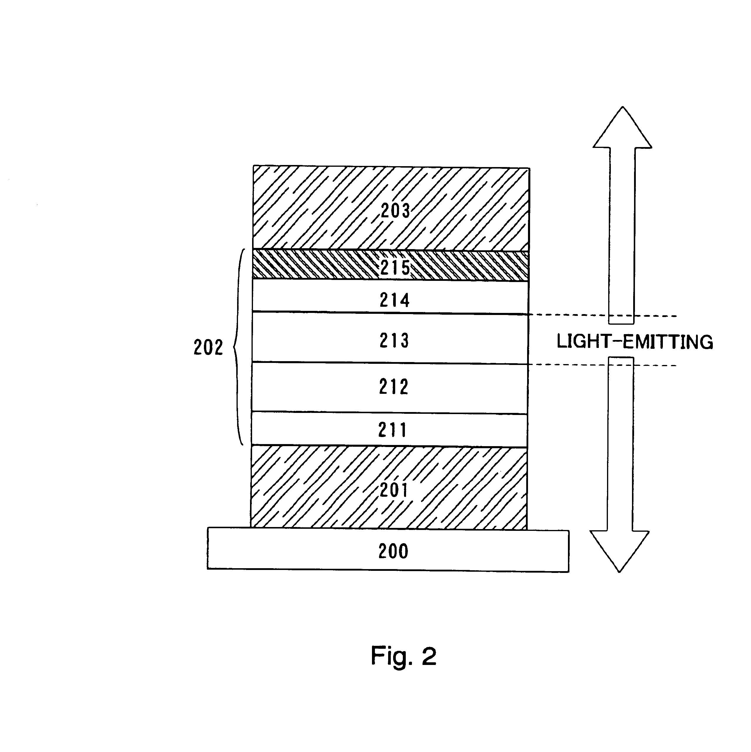
[0050]In the present embodiment, a light-emitting element according to the present invention in the case of a structure in which light generated in a layer including a luminescent material is emitted from both side of first and second electrodes of a light-emitting element (hereinafter, referred to as a both-emission structure), which has an electron injection layer provided in a portion of the layer including the luminescent material, will be described with reference to FIG. 2.

[0051]First, a first electrode 201 of a light-emitting element is formed on a substrate 200. In the present embodiment, the first electrode 201 functions as an anode. ITO that is a transparent conductive film is used as a material to form the first electrode 201 with a film thickness of 110 nm by sputtering.

[0052]Next, a layer 202 including a luminescent material is formed on the first electrode (anode) 201. The layer 202 including the luminescent material in the present embodiment has a laminat...

embodiment 2

(Embodiment 2)

[0062]In the present embodiment, a specific structure in which light is emitted from a second electrode to be formed a layer including a luminescent material (hereinafter, referred to as a top-emission structure) in the case of a structure where light generated in a layer including a luminescent material is emitted from one side of a light-emitting element will be described with reference to FIG. 3.

[0063]Only different portion from the structure in Embodiment 1 will be described here, and descriptions of component parts except a first electrode, which are the same as those of Embodiment 1, will be omitted.

[0064]A first electrode 301 in the present embodiment functions as an anode, from which no light generated in a layer 302 including a luminescent material is emitted. In other words, a nitride or carbide of an element belonging to one of Group 4, Group 5, and Group 6 of the periodic table of the elements, which has a large work function and shields light, such as tita...

embodiment 3

(Embodiment 3)

[0070]In the present invention, a structure in which light is emitted from a side of an electron injection layer 515 included in a layer 502 including a luminescent material as shown in FIG. 4 (hereinafter, referred to as a top-emission structure) can also be employed in the case of a structure where light generated in a layer including a luminescent material is emitted from one side of a light-emitting element as described in Embodiment 2.

[0071]In the same way as Embodiment 2, as a first electrode 501, a reflective conductive film 504 is formed on a substrate 500 and then, a transparent conductive film 505 is formed thereon. After forming the first electrode 501, a hole injection layer 511, a hole transport layer 512, a light-emitting layer 513, an electron transport layer 514, the electron injection layer 515, and a second electrode 503 are sequentially laminated in the same way as Embodiments 1 and 2.

[0072]In the case of the present embodiment, since the second elec...


PUM

PropertyMeasurementUnit
work functionaaaaaaaaaa
thicknessaaaaaaaaaa
work functionaaaaaaaaaa

Abstract

In the present invention, an electron injection composition for a light-emitting element, comprising a pyridine derivative represented by general formula 1 and at least one of an alkali metal, an alkali earth metal, and a transition metal, is used to form an electron injection layer in a portion of a layer including luminescent material in a light-emitting element, and it is also an object of the present invention to provide, by using the composition, a light-emitting element that has more superior characteristics and a longer lifetime as compared to conventional ones. (where each of R1 to R8 represents hydrogen, halogen, a cyano group, an alkyl group having 1 to 10 carbon atoms, a haloalkyl group having 1 to 10 carbon atoms, an alkoxyl group having 1 to 10 carbon atoms, a substituted or unsubstituted aryl group, or a substituted or unsubstituted heterocyclic group.)

Description

BACKGROUND OF THE INVENTION[0001]1. Field of the Invention[0002]The present invention relates to an electron injection composition for a light-emitting element, a light-emitting element formed with the use of the electron injection composition, and a light-emitting device that has the light-emitting element.[0003]2. Description of the Related Art[0004]A light-emitting element that uses a material as a light emitter, which has features such as a thin thickness and lightweight, a high speed response, and low DC voltage drive, has been expected to be applied to a next-generation flat panel display. In addition, it is said that a light-emitting device that has light-emitting elements arranged in a matrix shape is superior in having a wide view angle and a high level of visibility, as compared to a conventional liquid crystal display device.[0005]A light-emitting element is said to have an emission mechanism that: an electron injected from a cathode and a hole injected from an anode are ...

Claims


Application Information

Patent Timeline
Patent Type & Authority Patents(United States)
IPC IPC(8): C09K11/06H01L29/24H01L27/15H01L29/02H05B33/14H05B33/02H05B33/20H05B33/12H05B33/08H01L51/00H01L51/50H01L51/52H05B33/22H05B44/00
CPCH01L51/002H01L51/0067H01L51/0073H01L51/0081H01L51/5092H01L51/5221H01L2251/308H01L2251/5315H10K71/30H10K85/324H10K85/654H10K85/6574H10K50/171H10K50/82H10K2102/3026H10K2102/103H05B33/14
Inventor NAKAMURA, YASUO
Owner SEMICON ENERGY LAB CO LTD
Why Eureka
Try Eureka