Dual band antenna with increased sensitivity in a horizontal direction

Inactive Publication Date: 2005-07-05
ALPS ALPINE CO LTD
View PDF17 Cites 11 Cited by
  • Summary
  • Abstract
  • Description
  • Claims
  • Application Information

AI Technical Summary

Benefits of technology

[0013]According to the dual band antenna constructed above, by supplying high frequency power of a first frequency to the bottom portion of the power-supplying conductor plate, the first radiating conductor plate will be resonated like an inverted F type antenna, thus making it possible to obtain a radiation pattern with an increased gain in the horizontal direction. Moreover, by feeding the high frequency power of a second frequency to the bottom portion of the second radiating conductor plate, the second radiating conductor plate will be resonated like a monopole antenna so that a radiation pattern with an increased gain in the horizontal direction can be attained. This assures good sensitivity in the horizontal direction regardless of whether resonance occurs at the high frequency or the low frequency. Furthermore, it becomes possible to reduce the height of the second radiating conductor plate and thereby make the overall profile of the antenna low, because the first radiating conductor plate facing the top portion of the second radiating conductor plate serves as a capacitive load during resonance of the second radiating conductor plate. In addition, the resonance frequency of the second radiating conductor plate can be adjusted in a simple and precise manner, due to the fact that the degree of capacity coupling between the first and second radiating conductor plates may be changed by way of altering the gap between the top portion of the second radiating conductor plate and the first radiating conductor plate.
[0014]As an arrangement for changing the gap between the top portion of the second radiating conductor plate and the first radiating conductor plate, it may be contemplated, for example, that the second radiating conductor plate has an elastically deformable portion at its local area and a synthetic resin adjusting screw is threaded to the first radiating conductor

Problems solved by technology

Because a car-mounted communication device often receives and transmits horizontally advancing signal waves, employing the conventional dual band antenna 1 as a car-mounted communication antenna may result in the electrical waves of the second frequency f2

Method used


Image

  • Dual band antenna with increased sensitivity in a horizontal direction
  • Dual band antenna with increased sensitivity in a horizontal direction
  • Dual band antenna with increased sensitivity in a horizontal direction

Examples


Embodiment Construction

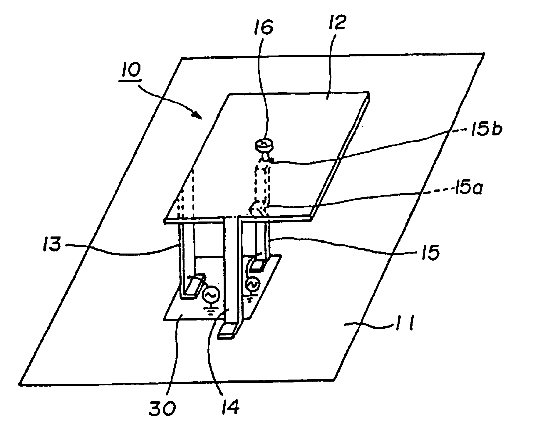
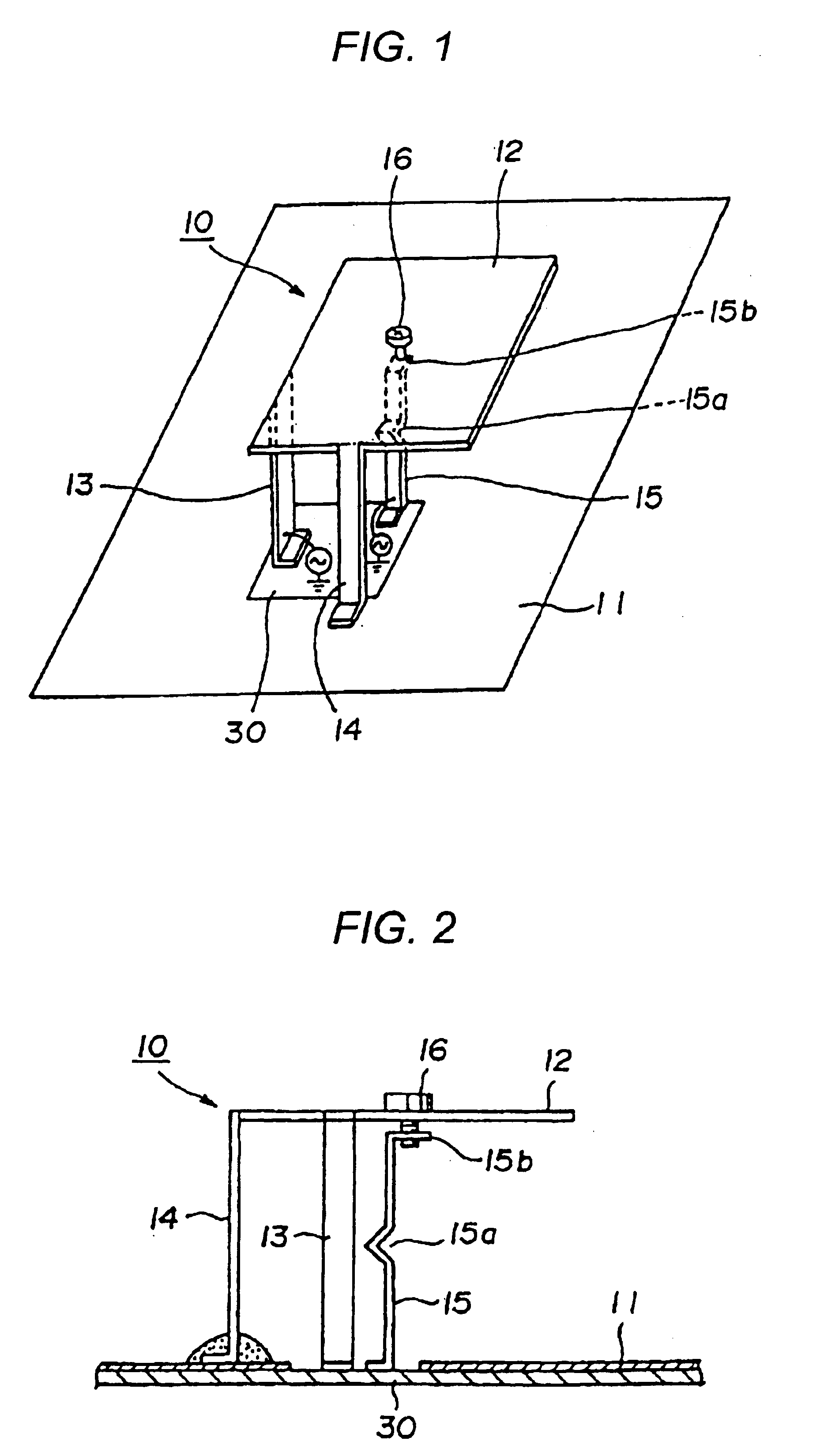
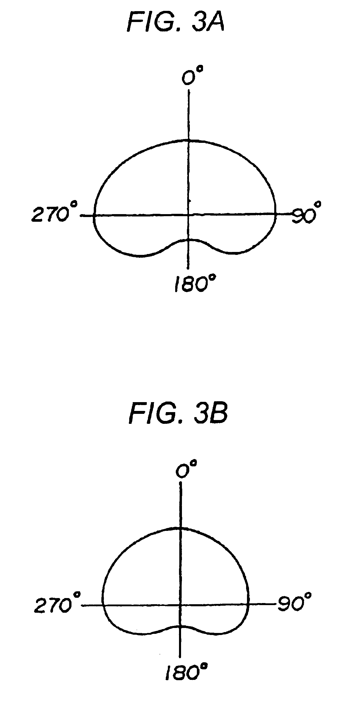
[0023]Certain preferred embodiments of the present invention will now be described with reference to the drawings. FIG. 1 is a perspective view of a dual band antenna according to a preferred embodiment of the present invention, FIG. 2 is a side elevational view of the dual band antenna shown in FIG. 1, and FIG. 3 is a characteristic view illustrating the radiation pattern of the dual band antenna shown in FIG. 1.

[0024]Referring to FIGS. 1 and 2, the dual band antenna 10 is a small-sized antenna adapted to operate both as an inverted F type antenna and a monopole antenna. The dual band antenna 10 is produced by way of mounting a press-formed, metallic conductor sheet (a copper sheet, for instance) of a predetermined configuration onto a grounding conductor 11 that is provided on the entire surface of a support substrate 30 in the form of, e.g., a copper foil. The dual band antenna 10 comprises a first radiating conductor plate 12 disposed substantially parallel to the grounding cond...


PUM


Abstract

A dual band antenna contains a first radiating conductor plate disposed substantially parallel to a grounding conductor, a power-supplying conductor plate extending downwards from the first radiating conductor plate, a connecting conductor plate for connecting the first radiating conductor plate to the grounding conductor, a second radiating conductor plate provided upright beneath the first radiating conductor plate and having a substantially wedge-shaped, elastically deformable portion, and a synthetic resin adjusting screw threaded to the first radiating conductor plate for depressing the top portion of the second radiating conductor plate downwards. The first and second radiating conductor plates resonate at first and second frequencies respectively (with f2>f1). The gap between the second radiating conductor plate and the first radiating conductor plate can be changed.

Description

[0001]This application claims the benefit of priority to Japanese Patent Application No. 2003-011389, herein incorporated by reference.BACKGROUND OF THE INVENTION[0002]1. Field of the Invention[0003]The present invention relates to a small-sized, dual band antenna capable of transmitting and receiving signal waves of two type frequency bands and adapted for easier assembly with a car-mounted communication device.[0004]2. Description of the Related Art[0005]Conventionally, as a dual band antenna suitable for miniaturization, an inverted F type antenna that can resonate with two kinds of frequencies, i.e., high and low frequencies by the action of notch portions provided on a radiating conductor plate (refer to Patent Document 1), has been proposed.[0006]FIG. 5 illustrates a conventional example. In FIG. 5, an inverted F type dual band antenna 1 includes a radiating conductor plate 2 with a rectangular notch portion 4. The radiating conductor plate 2 has an L-shaped conductor piece 2a...

Claims


Application Information

Patent Timeline
IPC IPC(8): H01Q9/04H01Q5/00H01Q21/28H01Q5/10H01Q5/35H01Q9/40H01Q13/08H01Q21/30
CPCH01Q9/0421H01Q5/40H01Q5/35H01Q9/0442A47J36/04A47J37/067
Inventor SHIKATA, MASARUSASAKI, KAZUHIROTANAKA, NORIO
Owner ALPS ALPINE CO LTD
Why Eureka
Try Eureka